
Manual
Page 1
GA-M55plus-S3G (rev. 3.0) AMD Socket AM2 Processor Motherboard User's Manual Rev. 3001 12ME-M55PS3G-3001R * The WEEE marking on the product indicates this product must not be disposed of with user's other household waste and must be handed over to a designated collection point for the recycling of waste electrical and electronic equipment!! * The WEEE marking applies only in European Union's member states.
GA-M55plus-S3G (rev. 3.0) AMD Socket AM2 Processor Motherboard User's Manual Rev. 3001 12ME-M55PS3G-3001R * The WEEE marking on the product indicates this product must not be disposed of with user's other household waste and must be handed over to a designated collection point for the recycling of waste electrical and electronic equipment!! * The WEEE marking applies only in European Union's member states.

Manual
Page 2
Motherboard GA-M55plus-S3G (rev. 3.0) Nov. 8, 2006 Motherboard GA-M55plus-S3G (rev. 3.0) Nov. 8, 2006
Motherboard GA-M55plus-S3G (rev. 3.0) Nov. 8, 2006 Motherboard GA-M55plus-S3G (rev. 3.0) Nov. 8, 2006
Manual
Page 4
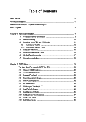
Table of Contents ItemChecklist ...6 OptionalAccessories ...6 GA-M55plus-S3G (rev. 3.0) Motherboard Layout 7 Block Diagram ...8 Chapter 1 Hardware Installation 9 1-1 Considerations Prior to Installation 9 1-2 Feature Summary 10 1-3 Installation of the CPU and CPU Cooler 12 1-3-1 Installation of the ...
Table of Contents ItemChecklist ...6 OptionalAccessories ...6 GA-M55plus-S3G (rev. 3.0) Motherboard Layout 7 Block Diagram ...8 Chapter 1 Hardware Installation 9 1-1 Considerations Prior to Installation 9 1-2 Feature Summary 10 1-3 Installation of the CPU and CPU Cooler 12 1-3-1 Installation of the ...
Manual
Page 7
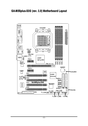
GA-M55plus-S3G (rev. 3.0) Motherboard Layout KB_MS Socket AM2 ATX COMA LPT VGA USB USB 1394 LAN ATX_12V AUDIO CPU_FAN F_AUDIO PCIE_1 Marvell 88E1116 nVIDIA® GeFore 6150 PCIE_16 DDRII_1 DDRII_2 DDRII_3 DDRII_4 CODEC PCIE_2 PCI1 PCI2 BATTERY BIOS nVIDIA® nForce 430 SATAII2_3 CD_IN SPDIF_IO PCI3 GA-M55plus-S3G TSB43AB23 IT8716 REV: 3.0 PCI4 CI SATAII0_1 IDE1 IDE2 F2_1394 PWR_LED FDD F1_1394 F_USB1 F_USB2 F_PANEL CLR_CMOS SYS_FAN - 7 -
GA-M55plus-S3G (rev. 3.0) Motherboard Layout KB_MS Socket AM2 ATX COMA LPT VGA USB USB 1394 LAN ATX_12V AUDIO CPU_FAN F_AUDIO PCIE_1 Marvell 88E1116 nVIDIA® GeFore 6150 PCIE_16 DDRII_1 DDRII_2 DDRII_3 DDRII_4 CODEC PCIE_2 PCI1 PCI2 BATTERY BIOS nVIDIA® nForce 430 SATAII2_3 CD_IN SPDIF_IO PCI3 GA-M55plus-S3G TSB43AB23 IT8716 REV: 3.0 PCI4 CI SATAII0_1 IDE1 IDE2 F2_1394 PWR_LED FDD F1_1394 F_USB1 F_USB2 F_PANEL CLR_CMOS SYS_FAN - 7 -
Manual
Page 10
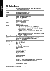
... connection of 4 SATA 3Gb/s devices - English 1-2 Feature Summary CPU Š Socket AM2 for additional 2 ports by cable Š 1 power LED connector Š 1 Chassis Intrusion connector GA-M55plus-S3G (rev. 3.0) Motherboard - 10 -
... connection of 4 SATA 3Gb/s devices - English 1-2 Feature Summary CPU Š Socket AM2 for additional 2 ports by cable Š 1 power LED connector Š 1 Chassis Intrusion connector GA-M55plus-S3G (rev. 3.0) Motherboard - 10 -
Manual
Page 12
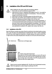
... it into the socket. Fig.1 Socket Lever Position lever at a 90 degree angle. Please use , otherwise overheating and permanent damage of the CPU may occur. 5. GA-M55plus-S3G (rev. 3.0) Motherboard - 12 - Please make sure the CPU cooler is positioned into its original position. Please take note of heat paste between the CPU and CPU...
... it into the socket. Fig.1 Socket Lever Position lever at a 90 degree angle. Please use , otherwise overheating and permanent damage of the CPU may occur. 5. GA-M55plus-S3G (rev. 3.0) Motherboard - 12 - Please make sure the CPU cooler is positioned into its original position. Please take note of heat paste between the CPU and CPU...
Manual
Page 14
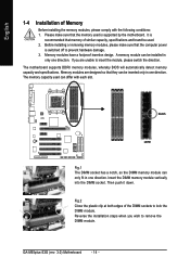
... the plastic clip at both edges of similar capacity, specifications and brand be used is switched off to insert the module, please switch the direction. GA-M55plus-S3G (rev. 3.0) Motherboard - 14 - English 1-4 Installation of Memory Before installing the memory modules, please comply with each slot. The motherboard supports DDRII memory modules, whereby BIOS will...
... the plastic clip at both edges of similar capacity, specifications and brand be used is switched off to insert the module, please switch the direction. GA-M55plus-S3G (rev. 3.0) Motherboard - 14 - English 1-4 Installation of Memory Before installing the memory modules, please comply with each slot. The motherboard supports DDRII memory modules, whereby BIOS will...
Manual
Page 16
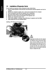
... expansion card. 6. When you try uninstall the VGA card, please gently press the latch as the picture to the left shows to release the card. GA-M55plus-S3G (rev. 3.0) Motherboard - 16 - Install related driver from the computer. 3. Press the expansion card firmly into the computer. 2. Make sure your VGA card is locked by following...
... expansion card. 6. When you try uninstall the VGA card, please gently press the latch as the picture to the left shows to release the card. GA-M55plus-S3G (rev. 3.0) Motherboard - 16 - Install related driver from the computer. 3. Press the expansion card firmly into the computer. 2. Make sure your VGA card is locked by following...
Manual
Page 18
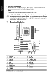
... for detailed software configuration information. 1-7 Connectors Introduction 31 2 8 17 15 10 14 6 16 7 4 5 1) ATX_12V 2) ATX (Power Connector) 3) CPU_FAN 4) SYS_FAN 5) FDD 6) IDE1/IDE2 7) SATAII0/1/2/3 8) F_AUDIO 9) F_PANEL GA-M55plus-S3G (rev. 3.0) Motherboard 13 12 11 9 10) CD_IN 11) PWR_LED 12) F_USB1/F_USB2 13) F1_1394/F2_1394 14) SPDIF_IO 15) CLR_CMOS 16) CI 17) BATTERY - 18 - Only microphones...
... for detailed software configuration information. 1-7 Connectors Introduction 31 2 8 17 15 10 14 6 16 7 4 5 1) ATX_12V 2) ATX (Power Connector) 3) CPU_FAN 4) SYS_FAN 5) FDD 6) IDE1/IDE2 7) SATAII0/1/2/3 8) F_AUDIO 9) F_PANEL GA-M55plus-S3G (rev. 3.0) Motherboard 13 12 11 9 10) CD_IN 11) PWR_LED 12) F_USB1/F_USB2 13) F1_1394/F2_1394 14) SPDIF_IO 15) CLR_CMOS 16) CI 17) BATTERY - 18 - Only microphones...
Manual
Page 20
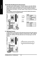
... note of FDD drives supported are designed with color-coded power connector wires. The types of the foolproof groove in the FDD connector. 33 1 34 2 GA-M55plus-S3G (rev. 3.0) Motherboard - 20 - Most coolers are : 360 KB, 720 KB, 1.2 MB, 1.44 MB and 2.88 MB. The black connector wire is used to connect the FDD...
... note of FDD drives supported are designed with color-coded power connector wires. The types of the foolproof groove in the FDD connector. 33 1 34 2 GA-M55plus-S3G (rev. 3.0) Motherboard - 20 - Most coolers are : 360 KB, 720 KB, 1.2 MB, 1.44 MB and 2.88 MB. The black connector wire is used to connect the FDD...
Manual
Page 22
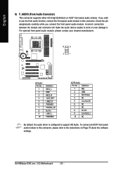
... to this connector, please refer to this connector. Incorrect connection between the module and connector will make the audio device unable to support HD Audio. GA-M55plus-S3G (rev. 3.0) Motherboard - 22 - To connect an AC97 front panel audio module to the instructions on Page 79 about the software settings. If you connect the front...
... to this connector, please refer to this connector. Incorrect connection between the module and connector will make the audio device unable to support HD Audio. GA-M55plus-S3G (rev. 3.0) Motherboard - 22 - To connect an AC97 front panel audio module to the instructions on Page 79 about the software settings. If you connect the front...
Manual
Page 24
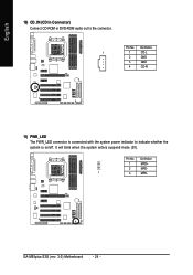
English 10) CD_IN (CD In Connector) Connect CD-ROM or DVD-ROM audio out to indicate whether the system is connected with the system power indicator to the connector. Definition 1 1 CD-L 2 GND 3 GND 4 CD-R 11) PWR_LED The PWR_LED connector is on/off. GA-M55plus-S3G (rev. 3.0) Motherboard - 24 - Definition 1 MPD+ 2 MPD- 1 3 MPD- Pin No. It will blink when the system enters suspend mode (S1). Pin No.
English 10) CD_IN (CD In Connector) Connect CD-ROM or DVD-ROM audio out to indicate whether the system is connected with the system power indicator to the connector. Definition 1 1 CD-L 2 GND 3 GND 4 CD-R 11) PWR_LED The PWR_LED connector is on/off. GA-M55plus-S3G (rev. 3.0) Motherboard - 24 - Definition 1 MPD+ 2 MPD- 1 3 MPD- Pin No. It will blink when the system enters suspend mode (S1). Pin No.
Manual
Page 26
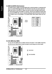
... device unable to an external Dolby Digital Decoder. Default doesn't include the jumper to its default values by this header. Open: Normal Short: Clear CMOS GA-M55plus-S3G (rev. 3.0) Motherboard - 26 - Use S/PDIF IN feature only when your stereo system has digital input function. Be careful with the polarity of this header. To clear...
... device unable to an external Dolby Digital Decoder. Default doesn't include the jumper to its default values by this header. Open: Normal Short: Clear CMOS GA-M55plus-S3G (rev. 3.0) Motherboard - 26 - Use S/PDIF IN feature only when your stereo system has digital input function. Be careful with the polarity of this header. To clear...
Manual
Page 28
English GA-M55plus-S3G (rev. 3.0) Motherboard - 28 -
English GA-M55plus-S3G (rev. 3.0) Motherboard - 28 -
Manual
Page 30
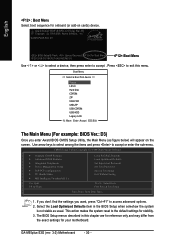
... Defaults Set Supervisor Password Set User Password Save & Exit Setup Exit Without Saving KLJI: Select Item F10: Save & Exit Setup Time, Date, Hard Disk Type... 1. GA-M55PLUS-S3G D3 . . . . :BIOS Setup/Q-Flash, : Xpress Recovery2, :For Boot Menu 10/25/2006-C51-MCP51-6A61HG0MC-00 :Boot Menu Use < > or < ...The BIOS Setup menus described in the BIOS Setup when somehow the system is not stable as figure below) will appear on cards) device. GA-M55plus-S3G (rev. 3.0) Motherboard - 30 - If you don't find the settings you enter Award BIOS CMOS Setup Utility, the Main Menu (as usual. ...
... Defaults Set Supervisor Password Set User Password Save & Exit Setup Exit Without Saving KLJI: Select Item F10: Save & Exit Setup Time, Date, Hard Disk Type... 1. GA-M55PLUS-S3G D3 . . . . :BIOS Setup/Q-Flash, : Xpress Recovery2, :For Boot Menu 10/25/2006-C51-MCP51-6A61HG0MC-00 :Boot Menu Use < > or < ...The BIOS Setup menus described in the BIOS Setup when somehow the system is not stable as figure below) will appear on cards) device. GA-M55plus-S3G (rev. 3.0) Motherboard - 30 - If you don't find the settings you enter Award BIOS CMOS Setup Utility, the Main Menu (as usual. ...
Manual
Page 32
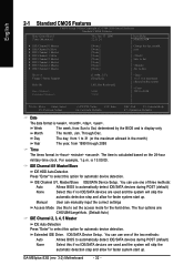
... options are: CHS/LBA/Large/Auto. (Default:Auto) IDE Channel 2, 3, 4, 5 Master IDE Auto-Detection Press "Enter" to set the access mode for automatic device detection. GA-M55plus-S3G (rev. 3.0) Motherboard - 32 - You can use one of the two methods: Auto Allows BIOS to automatically detect IDE/SATA devices during POST (default) None Select this...
... options are: CHS/LBA/Large/Auto. (Default:Auto) IDE Channel 2, 3, 4, 5 Master IDE Auto-Detection Press "Enter" to set the access mode for automatic device detection. GA-M55plus-S3G (rev. 3.0) Motherboard - 32 - You can use one of the two methods: Auto Allows BIOS to automatically detect IDE/SATA devices during POST (default) None Select this...
Manual
Page 34
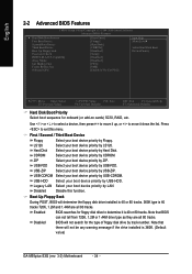
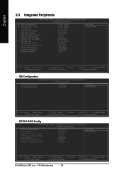
... device priority by USB-CDROM. Disabled BIOS will determine the floppy disk drive installed is 40 or 80 tracks. 360K type is 360K. (Default value) GA-M55plus-S3G (rev. 3.0) Motherboard - 34 - Capability Away Mode Init Display First Frame Buffer Size Onboard GPU [Press Enter] [Floppy] [Hard Disk] [CDROM] [Disabled] [Setup] [Disabled] [Disabled] [PEG] [64M...
... device priority by USB-CDROM. Disabled BIOS will determine the floppy disk drive installed is 40 or 80 tracks. 360K type is 360K. (Default value) GA-M55plus-S3G (rev. 3.0) Motherboard - 34 - Capability Away Mode Init Display First Frame Buffer Size Onboard GPU [Press Enter] [Floppy] [Hard Disk] [CDROM] [Disabled] [Setup] [Disabled] [Disabled] [PEG] [64M...
Manual
Page 36
...] Enabled Enabled [Enabled] Enabled Enabled Item Help Menu Level` KLJI: Move Enter: Select F5: Previous Values +/-/PU/PD: Value F10: Save F6: Fail-Safe Defaults GA-M55plus-S3G (rev. 3.0) Motherboard - 36 -
...] Enabled Enabled [Enabled] Enabled Enabled Item Help Menu Level` KLJI: Move Enter: Select F5: Previous Values +/-/PU/PD: Value F10: Save F6: Fail-Safe Defaults GA-M55plus-S3G (rev. 3.0) Motherboard - 36 -
Manual
Page 38
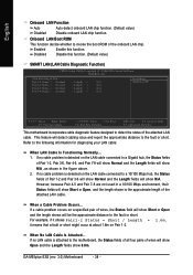
GA-M55plus-S3G (rev. 3.0) Motherboard - 38 - Pair1-2 Status = Normal / Length = N/A Pair3-6 Status = Normal / Length = N/A Pair4-5 Status = Normal / Length = N/A Pair7-8 Status = Normal / Length = N/A Item Help Menu Level` KLJI: Move Enter: ...
GA-M55plus-S3G (rev. 3.0) Motherboard - 38 - Pair1-2 Status = Normal / Length = N/A Pair3-6 Status = Normal / Length = N/A Pair4-5 Status = Normal / Length = N/A Pair7-8 Status = Normal / Length = N/A Item Help Menu Level` KLJI: Move Enter: ...
Manual
Page 40
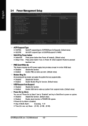
... Modem Ring On USB Resume from Suspend Power-On by Alarm x Day of Month Alarm : Everyday, 1~31 Time (hh: mm: ss) Alarm : (0~23) : (0~59) : (0~59) GA-M55plus-S3G (rev. 3.0) Motherboard - 40 - Disabled Disable this function. Enter suspend if button is Enabled. PME Event Wake Up This feature requires an ATX power supply that provides...
... Modem Ring On USB Resume from Suspend Power-On by Alarm x Day of Month Alarm : Everyday, 1~31 Time (hh: mm: ss) Alarm : (0~23) : (0~59) : (0~59) GA-M55plus-S3G (rev. 3.0) Motherboard - 40 - Disabled Disable this function. Enter suspend if button is Enabled. PME Event Wake Up This feature requires an ATX power supply that provides...


