
User Manual
Page 4
Table of Contents GA-K8VT890-9 Motherboard Layout 6 Block Diagram ...7 Chapter 1 Hardware Installation 9 1-1 Considerations Prior to Installation 9 1-2 Feature Summary 10 1-3 Installation of the CPU and Fan Heat Sink 12 1-3-1 Installation of ... 2-5 PnP/PCI Configurations 39 2-6 PC Health Status 40 2-7 Frequency/Voltage Control 41 2-8 Top Performance 42 2-9 Load Fail-Safe Defaults 42 2-10 Load Optimized Defaults 43 2-11 Set Supervisor/User Password 43 2-12 Save & Exit Setup 44 2-13 Exit Without Saving 44 - 4 -
Table of Contents GA-K8VT890-9 Motherboard Layout 6 Block Diagram ...7 Chapter 1 Hardware Installation 9 1-1 Considerations Prior to Installation 9 1-2 Feature Summary 10 1-3 Installation of the CPU and Fan Heat Sink 12 1-3-1 Installation of ... 2-5 PnP/PCI Configurations 39 2-6 PC Health Status 40 2-7 Frequency/Voltage Control 41 2-8 Top Performance 42 2-9 Load Fail-Safe Defaults 42 2-10 Load Optimized Defaults 43 2-11 Set Supervisor/User Password 43 2-12 Save & Exit Setup 44 2-13 Exit Without Saving 44 - 4 -

User Manual
Page 11
... (Note 4) EasyTune 5 functions may vary depending on the Win 2000/XP operating systems Use of up to 150 MB/s - Hardware Installation supported on different motherboards. - 11 - English Onboard SATA RAID Š BIOS Š Š Additional Features Š Š Overclocking Š Š Form Factor Š Onboard VT8237R chipset (SATA0, SATA1) - supports data...
... (Note 4) EasyTune 5 functions may vary depending on the Win 2000/XP operating systems Use of up to 150 MB/s - Hardware Installation supported on different motherboards. - 11 - English Onboard SATA RAID Š BIOS Š Š Additional Features Š Š Overclocking Š Š Form Factor Š Onboard VT8237R chipset (SATA0, SATA1) - supports data...

User Manual
Page 18
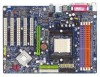
English 1-7 Connectors Introduction 1 3 2 11 13 12 14 1) ATX_12V 2) ATX (Power Connector) 3) CPU_FAN 4) SYS_FAN 5) FDD 6) IDE1 / IDE2 7) SATA0 / SATA1 8) PWR_LED 9) BATTERY 6 7 5 10 8 4 9 15 17 16 10) F_PANEL 11) F_AUDIO 12) CD_IN 13) SUR_CEN 14) SPDIF_IO 15) F_USB1 / F_USB2 16) CLR_CMOS 17) CI GA-K8VT890-9 Motherboard - 18 -
English 1-7 Connectors Introduction 1 3 2 11 13 12 14 1) ATX_12V 2) ATX (Power Connector) 3) CPU_FAN 4) SYS_FAN 5) FDD 6) IDE1 / IDE2 7) SATA0 / SATA1 8) PWR_LED 9) BATTERY 6 7 5 10 8 4 9 15 17 16 10) F_PANEL 11) F_AUDIO 12) CD_IN 13) SUR_CEN 14) SPDIF_IO 15) F_USB1 / F_USB2 16) CLR_CMOS 17) CI GA-K8VT890-9 Motherboard - 18 -

User Manual
Page 19
... to handle the system voltage requirements. Definition 1 3.3V 12 24 2 3.3V 3 GND 4 +5V 5 GND 6 +5V 7 GND 8 Power Good 9 5V SB(stand by +5V) 10 +12V 11 +12V 12 3.3V(Only for 24pins ATX) 13 3.3V 1 13 14 -12V 15 GND 16 PS_ON(soft On/Off) 17 GND 18 GND 19 GND...
... to handle the system voltage requirements. Definition 1 3.3V 12 24 2 3.3V 3 GND 4 +5V 5 GND 6 +5V 7 GND 8 Power Good 9 5V SB(stand by +5V) 10 +12V 11 +12V 12 3.3V(Only for 24pins ATX) 13 3.3V 1 13 14 -12V 15 GND 16 PS_ON(soft On/Off) 17 GND 18 GND 19 GND...
User Manual
Page 24
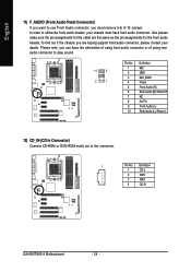
... cable are buying support front audio connector, please contact your chassis must remove 5-6, 9-10 Jumper. Definition 1 CD-L 2 GND 3 GND 4 CD-R GA-K8VT890-9 Motherboard - 24 - In order to the connector. 1 Pin No. English 11) F_AUDIO (Front Audio Panel Connector) If you want to use Front Audio connector, you must have the alternative of using...
... cable are buying support front audio connector, please contact your chassis must remove 5-6, 9-10 Jumper. Definition 1 CD-L 2 GND 3 GND 4 CD-R GA-K8VT890-9 Motherboard - 24 - In order to the connector. 1 Pin No. English 11) F_AUDIO (Front Audio Panel Connector) If you want to use Front Audio connector, you must have the alternative of using...

User Manual
Page 39
...] Item Help Menu Level` KLJI: Move Enter: Select F5: Previous Values PCI 1 IRQ Assignment Auto 3,4,5,7,9,10,11,12,14,15 PCI 2 IRQ Assignment Auto 3,4,5,7,9,10,11,12,14,15 PCI 3 IRQ Assignment Auto 3,4,5,7,9,10,11,12,14,15 +/-/PU/PD: Value F10: Save F6: Fail-Safe Defaults ESC: Exit F1: General Help... F7: Optimized Defaults Auto assign IRQ to PCI 1. (Default value) Set IRQ 3,4,5,7,9,10,11,12,14,15 to PCI 2. Auto assign IRQ to PCI 2. (Default value) Set IRQ 3,4,5,7,9,10,11,12,14,15 to PCI 1/5. Auto assign IRQ to PCI 3. (Default value) Set IRQ 3,4,5,7,9,10...
...] Item Help Menu Level` KLJI: Move Enter: Select F5: Previous Values PCI 1 IRQ Assignment Auto 3,4,5,7,9,10,11,12,14,15 PCI 2 IRQ Assignment Auto 3,4,5,7,9,10,11,12,14,15 PCI 3 IRQ Assignment Auto 3,4,5,7,9,10,11,12,14,15 +/-/PU/PD: Value F10: Save F6: Fail-Safe Defaults ESC: Exit F1: General Help... F7: Optimized Defaults Auto assign IRQ to PCI 1. (Default value) Set IRQ 3,4,5,7,9,10,11,12,14,15 to PCI 2. Auto assign IRQ to PCI 2. (Default value) Set IRQ 3,4,5,7,9,10,11,12,14,15 to PCI 1/5. Auto assign IRQ to PCI 3. (Default value) Set IRQ 3,4,5,7,9,10...

User Manual
Page 43
... to abort the selection and not enter a password. When enabled, the Supervisor password is required for BIOS and Chipset Features which the system automatically detects. 2-11 Set Supervisor/User Password CMOS Setup Utility-Copyright (C) 1984-2004 Award Software ` Standard CMOS Features ` Advanced BIOS Features ` Integrated Peripherals ` Power Management Setup ` PnP/PCI...
... to abort the selection and not enter a password. When enabled, the Supervisor password is required for BIOS and Chipset Features which the system automatically detects. 2-11 Set Supervisor/User Password CMOS Setup Utility-Copyright (C) 1984-2004 Award Software ` Standard CMOS Features ` Advanced BIOS Features ` Integrated Peripherals ` Power Management Setup ` PnP/PCI...

User Manual
Page 49
... use tools such as 1) Overclocking for monitoring system status.(Note) User Interface Overview Button / Display 1. Smart-Fan 4. GIGABYTE Logo 10. Help button 11. Overclocking 2. Function display LEDs 9. PC Health 5. Featuring several powerful yet easy to GIGABYTE website Display EasyTuneTM 5 Help file Quit or Minimize EasyTuneTM 5 software (Note) EasyTune 5 functions may vary depending on...
... use tools such as 1) Overclocking for monitoring system status.(Note) User Interface Overview Button / Display 1. Smart-Fan 4. GIGABYTE Logo 10. Help button 11. Overclocking 2. Function display LEDs 9. PC Health 5. Featuring several powerful yet easy to GIGABYTE website Display EasyTuneTM 5 Help file Quit or Minimize EasyTuneTM 5 software (Note) EasyTune 5 functions may vary depending on...

User Manual
Page 77
.... Take out the battery gently and put it aside for about 10 minutes (Or you are hidden in the battery holder to http://www.gigabyte.com.tw Question 1: I clear CMOS? Answer: Please make sure the speaker you can take off power. 2. To check general asked questions... A20 failure 7 beeps Processor exception interrupt error 8 beeps Display memory read/write failure 9 beeps ROM checksum error 10 beeps CMOS shutdown register read/write error 11 beeps Cache memory bad AWARD BIOS Beep Codes 1 short: System boots successfully 2 short: CMOS setting error 1 long 1 short: DRAM or M/B error ...
.... Take out the battery gently and put it aside for about 10 minutes (Or you are hidden in the battery holder to http://www.gigabyte.com.tw Question 1: I clear CMOS? Answer: Please make sure the speaker you can take off power. 2. To check general asked questions... A20 failure 7 beeps Processor exception interrupt error 8 beeps Display memory read/write failure 9 beeps ROM checksum error 10 beeps CMOS shutdown register read/write error 11 beeps Cache memory bad AWARD BIOS Beep Codes 1 short: System boots successfully 2 short: CMOS setting error 1 long 1 short: DRAM or M/B error ...