Manual
Page 1
GA-H67M-UD2H-B3 LGA1155 socket motherboard for Intel® Core™ i7 processors/ Intel® Core™ i5 processors/Intel® Core™ i3 processors/ Intel® Pentium® processors/Intel® Celeron® processors User's Manual Rev. 1101 12ME-H67M2HB-1101R
GA-H67M-UD2H-B3 LGA1155 socket motherboard for Intel® Core™ i7 processors/ Intel® Core™ i5 processors/Intel® Core™ i3 processors/ Intel® Pentium® processors/Intel® Celeron® processors User's Manual Rev. 1101 12ME-H67M2HB-1101R
Manual
Page 2
Motherboard GA-H67M-UD2H-B3 Jan. 18, 2011 Motherboard GA-H67M-UD2H-B3 Jan. 18, 2011
Motherboard GA-H67M-UD2H-B3 Jan. 18, 2011 Motherboard GA-H67M-UD2H-B3 Jan. 18, 2011
Manual
Page 4
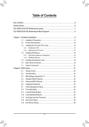
Table of Contents Box Contents...6 Optional Items...6 GA-H67M-UD2H-B3 Motherboard Layout 7 GA-H67M-UD2H-B3 Motherboard Block Diagram 8 Chapter 1 Hardware Installation 9 1-1 Installation Precautions 9 1-2 Product Specifications 10 1-3 Installing the CPU and CPU Cooler 13 1-3-1 Installing the CPU 13 1-3-2 Installing the CPU ...
Table of Contents Box Contents...6 Optional Items...6 GA-H67M-UD2H-B3 Motherboard Layout 7 GA-H67M-UD2H-B3 Motherboard Block Diagram 8 Chapter 1 Hardware Installation 9 1-1 Installation Precautions 9 1-2 Product Specifications 10 1-3 Installing the CPU and CPU Cooler 13 1-3-1 Installing the CPU 13 1-3-2 Installing the CPU ...
Manual
Page 6
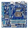
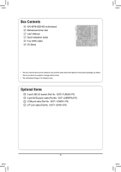
Optional Items 2-port USB 2.0 bracket (Part No. 12CR1-1UB030-5*R) 2-port SATA power cable (Part No. 12CF1-2SERPW-0*R) COM port cable (Part No. 12CF1-1CM001-3*R) LPT port cable (Part No. 12CF1-1LP001-0*R) - 6 - Box Contents GA-H67M-UD2H-B3 motherboard Motherboard driver disk User's Manual Quick Installation Guide Four SATA cables I/O Shield • The box contents above are subject to change without notice. • The motherboard image is for reference only and the actual items shall depend on the product package you obtain. The box contents are for reference only.
Optional Items 2-port USB 2.0 bracket (Part No. 12CR1-1UB030-5*R) 2-port SATA power cable (Part No. 12CF1-2SERPW-0*R) COM port cable (Part No. 12CF1-1CM001-3*R) LPT port cable (Part No. 12CF1-1LP001-0*R) - 6 - Box Contents GA-H67M-UD2H-B3 motherboard Motherboard driver disk User's Manual Quick Installation Guide Four SATA cables I/O Shield • The box contents above are subject to change without notice. • The motherboard image is for reference only and the actual items shall depend on the product package you obtain. The box contents are for reference only.
Manual
Page 7
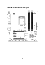
GA-H67M-UD2H-B3 Motherboard Layout DDR3_1 DDR3_2 DDR3_3 DDR3_4 KB_USB ATX_12V LGA1155 PHASE LED VGA_DVI HDMI_SPDIF USB30_20 USB_LAN AUDIO CPU_FAN PCIEX16 GA-H67M-UD2H-B3 Realtek RTL8111E PCIEX1_1 PCIEX1_2 CODEC PCIEX4 SPDIF_O F_AUDIO F_USB4 BAT F_USB3 Intel® H67 F_USB2 F_USB1 ATX LPT B_BIOS M_BIOS CLR_CMOS iTE IT8728 SATA3_0 SATA3_1 SATA2_2 SATA2_3 SYS_FAN SATA2_4 SATA2_5 F_PANEL COM - 7 -
GA-H67M-UD2H-B3 Motherboard Layout DDR3_1 DDR3_2 DDR3_3 DDR3_4 KB_USB ATX_12V LGA1155 PHASE LED VGA_DVI HDMI_SPDIF USB30_20 USB_LAN AUDIO CPU_FAN PCIEX16 GA-H67M-UD2H-B3 Realtek RTL8111E PCIEX1_1 PCIEX1_2 CODEC PCIEX4 SPDIF_O F_AUDIO F_USB4 BAT F_USB3 Intel® H67 F_USB2 F_USB1 ATX LPT B_BIOS M_BIOS CLR_CMOS iTE IT8728 SATA3_0 SATA3_1 SATA2_2 SATA2_3 SYS_FAN SATA2_4 SATA2_5 F_PANEL COM - 7 -
Manual
Page 8
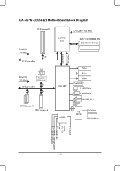
GA-H67M-UD2H-B3 Motherboard Block Diagram 1 PCI Express x16 PCIe CLK (100 MHz) x16 PCI Express Bus PCIe CLK (100 MHz) LAN RJ45 Realtek RTL8111E x1 PCI Express Bus x1 x4 2 PCI Express x1 1 PCI Express x4 LGA1155 CPU CPU CLK+/- (100 MHz) DDR3 1333/1066/800 MHz Dual Channel Memory DMI Interface FDI Interface Intel® H67 D-Sub DVI-D HDMI Dual BIOS 2 SATA 6Gb/s 4 SATA 3Gb/s 14 USB 2.0/1.1 CODEC LPC Bus iTE IT8728 COM Port PS/2 KB/Mouse Surround Speaker Out Center/Subwoofer Speaker Out Side Speaker Out MIC Line Out Line In S/PDIF Out - 8 -
GA-H67M-UD2H-B3 Motherboard Block Diagram 1 PCI Express x16 PCIe CLK (100 MHz) x16 PCI Express Bus PCIe CLK (100 MHz) LAN RJ45 Realtek RTL8111E x1 PCI Express Bus x1 x4 2 PCI Express x1 1 PCI Express x4 LGA1155 CPU CPU CLK+/- (100 MHz) DDR3 1333/1066/800 MHz Dual Channel Memory DMI Interface FDI Interface Intel® H67 D-Sub DVI-D HDMI Dual BIOS 2 SATA 6Gb/s 4 SATA 3Gb/s 14 USB 2.0/1.1 CODEC LPC Bus iTE IT8728 COM Port PS/2 KB/Mouse Surround Speaker Out Center/Subwoofer Speaker Out Side Speaker Out MIC Line Out Line In S/PDIF Out - 8 -
Manual
Page 32
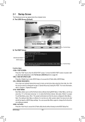
... computer boots. To exit Boot Menu, press . A. The POST Screen Award Modular BIOS v6.00PG Copyright (C) 1984-2010, Award Software, Inc. Motherboard Model BIOS Version H67M-UD2H-B3 F4d . . . . : BIOS Setup : XpressRecovery2 : Boot Menu : Qflash 12/31/2010-H67-7A89UG0GC-00 Function Keys Function Keys Function Keys: : POST SCREEN Press the key to...
... computer boots. To exit Boot Menu, press . A. The POST Screen Award Modular BIOS v6.00PG Copyright (C) 1984-2010, Award Software, Inc. Motherboard Model BIOS Version H67M-UD2H-B3 F4d . . . . : BIOS Setup : XpressRecovery2 : Boot Menu : Qflash 12/31/2010-H67-7A89UG0GC-00 Function Keys Function Keys Function Keys: : POST SCREEN Press the key to...
Manual
Page 64
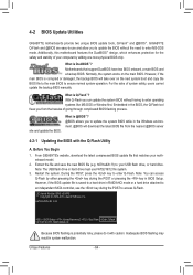
... of system safety, users cannot update the backup BIOS manually. What is DualBIOS™? Unique Features - 64 - 4-2 BIOS Update Utilities GIGABYTE motherboards provide two unique BIOS update tools, Q-Flash™ and @BIOS™. With Q-Flash you from the nearest @BIOS server 4-2-1 .... Extract the file and save the new BIOS file (e.g. During the POST, press the key to ensure normal system operation. Before You Begin 1. H67M-UD2H-B3 F4d . . . . : BIOS Setup : XpressRecovery2 : Boot Menu : Qflash 12/31/2010-H67-7A89UG0GC-00 Because BIOS flashing is @BIOS™...
... of system safety, users cannot update the backup BIOS manually. What is DualBIOS™? Unique Features - 64 - 4-2 BIOS Update Utilities GIGABYTE motherboards provide two unique BIOS update tools, Q-Flash™ and @BIOS™. With Q-Flash you from the nearest @BIOS server 4-2-1 .... Extract the file and save the new BIOS file (e.g. During the POST, press the key to ensure normal system operation. Before You Begin 1. H67M-UD2H-B3 F4d . . . . : BIOS Setup : XpressRecovery2 : Boot Menu : Qflash 12/31/2010-H67-7A89UG0GC-00 Because BIOS flashing is @BIOS™...


