Manual
Page 5
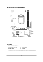
GA-H61M-DS2 Motherboard Layout KB_MS ATX_12V LGA1155 VGA CPU_FAN R_USB ATX USB_LAN DDR3_2 DDR3_1 Atheros GbE LAN AUDIO BAT GA-H61M-DS2 F_AUDIO PCIEX16 SATA2_3 SATA2_1 M_BIOS PCIEX1_1 iTE IT8728 B_BIOS CODEC SYS_FAN PCIEX1_2 Intel® H61 COMA CLR_CMOS LPT F_USB1 F_USB2 F_PANEL SATA2_0 SATA2_2 Box Contents GA-H61M-DS2 motherboard Motherboard driver disk User's Manual Two SATA cables I/O Shield The box contents above are for reference only and the actual items shall depend on the product package you obtain. - 5 -
GA-H61M-DS2 Motherboard Layout KB_MS ATX_12V LGA1155 VGA CPU_FAN R_USB ATX USB_LAN DDR3_2 DDR3_1 Atheros GbE LAN AUDIO BAT GA-H61M-DS2 F_AUDIO PCIEX16 SATA2_3 SATA2_1 M_BIOS PCIEX1_1 iTE IT8728 B_BIOS CODEC SYS_FAN PCIEX1_2 Intel® H61 COMA CLR_CMOS LPT F_USB1 F_USB2 F_PANEL SATA2_0 SATA2_2 Box Contents GA-H61M-DS2 motherboard Motherboard driver disk User's Manual Two SATA cables I/O Shield The box contents above are for reference only and the actual items shall depend on the product package you obtain. - 5 -
Manual
Page 6
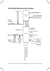
GA-H61M-DS2 Motherboard Block Diagram 1 PCI Express x16 CPU CLK+/- (100 MHz) LGA1155 CPU DDR3 1333/1066/800 MHz Dual Channel Memory PCIe CLK (100 MHz) x16 PCI Express Bus DMI 2.0 FDI D-Sub PCI Express Bus x1 x1 PCIe CLK Atheros GbE LAN (100 MHz) RJ45 2 PCI Express x1 LAN Intel® H61 Dual BIOS 4 SATA 3Gb/s 8 USB 2.0/1.1 LPC Bus iTE IT8728 LPT COM Port CODEC PS/2 KB/Mouse MIC (Center/Subwoofer Speaker Out) Line Out (Front Speaker Out) Line In (Rear Speaker Out) - 6 -
GA-H61M-DS2 Motherboard Block Diagram 1 PCI Express x16 CPU CLK+/- (100 MHz) LGA1155 CPU DDR3 1333/1066/800 MHz Dual Channel Memory PCIe CLK (100 MHz) x16 PCI Express Bus DMI 2.0 FDI D-Sub PCI Express Bus x1 x1 PCIe CLK Atheros GbE LAN (100 MHz) RJ45 2 PCI Express x1 LAN Intel® H61 Dual BIOS 4 SATA 3Gb/s 8 USB 2.0/1.1 LPC Bus iTE IT8728 LPT COM Port CODEC PS/2 KB/Mouse MIC (Center/Subwoofer Speaker Out) Line Out (Front Speaker Out) Line In (Rear Speaker Out) - 6 -
Manual
Page 13
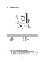
1-7 Internal Connectors 1 3 12 7 4 10 98 2 5 11 6 1) ATX_12V 2) ATX 3) CPU_FAN 4) SYS_FAN 5) SATA2_0/1/2/3 6) F_PANEL 7) F_AUDIO 8) F_USB1/2 9) COMA 10) LPT 11) CLR_CMOS 12) BAT Read the following guidelines before turning on the computer, make sure your devices are compliant with the connectors you wish to ...
1-7 Internal Connectors 1 3 12 7 4 10 98 2 5 11 6 1) ATX_12V 2) ATX 3) CPU_FAN 4) SYS_FAN 5) SATA2_0/1/2/3 6) F_PANEL 7) F_AUDIO 8) F_USB1/2 9) COMA 10) LPT 11) CLR_CMOS 12) BAT Read the following guidelines before turning on the computer, make sure your devices are compliant with the connectors you wish to ...

Manual
Page 18
For purchasing the optional LPT port cable, please contact the local dealer. 25 1 26 2 Pin No. 1 2 3 4 5 6 7 8 9 10 11 12 13 Definition STBAFDPD0 ERRPD1 INITPD2 SLINPD3 GND PD4 GND PD5 Pin ... GND ACKGND BUSY GND PE No Pin SLCT GND - 18 - 9) COMA (Serial Port Header) The COM header can provide one serial port via an optional LPT port cable. For purchasing the optional COM port cable, please contact the local dealer. 9 1 10 2 DEBUG PORT Pin No. 1 2 3 4 5 6 7 8 9 10 Definition NDCDNSIN NSOUT NDTRGND NDSRNRTSNCTSNRINo...
For purchasing the optional LPT port cable, please contact the local dealer. 25 1 26 2 Pin No. 1 2 3 4 5 6 7 8 9 10 11 12 13 Definition STBAFDPD0 ERRPD1 INITPD2 SLINPD3 GND PD4 GND PD5 Pin ... GND ACKGND BUSY GND PE No Pin SLCT GND - 18 - 9) COMA (Serial Port Header) The COM header can provide one serial port via an optional LPT port cable. For purchasing the optional COM port cable, please contact the local dealer. 9 1 10 2 DEBUG PORT Pin No. 1 2 3 4 5 6 7 8 9 10 Definition NDCDNSIN NSOUT NDTRGND NDSRNRTSNCTSNRINo...
Manual
Page 32
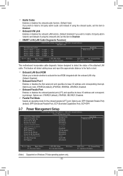
... distance to detect the status of using the onboard LAN, set this item to Disabled. Onboard Parallel Port Enables or disables the onboard parallel port (LPT) and specifies its base I /O address and corresponding interrupt. ESC: Exit F1: General Help F7: Optimized Defaults Onboard LAN Boot ROM Allows you wish to install...
... distance to detect the status of using the onboard LAN, set this item to Disabled. Onboard Parallel Port Enables or disables the onboard parallel port (LPT) and specifies its base I /O address and corresponding interrupt. ESC: Exit F1: General Help F7: Optimized Defaults Onboard LAN Boot ROM Allows you wish to install...