Manual
Page 9
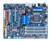
...motherboard S/N (Serial Number) sticker or warranty sticker provided by unplugging the power cord from the motherboard, make sure the power supply has been turned off. • Before turning on the power, make sure the power supply voltage has been set according to the local voltage standard. • ... or have it on top of an antistatic pad or within an electrostatic shielding container. • Before unplugging the power supply cable from the power outlet before installing or removing the motherboard or other hardware components. • When connecting hardware components to the internal...
...motherboard S/N (Serial Number) sticker or warranty sticker provided by unplugging the power cord from the motherboard, make sure the power supply has been turned off. • Before turning on the power, make sure the power supply voltage has been set according to the local voltage standard. • ... or have it on top of an antistatic pad or within an electrostatic shielding container. • Before unplugging the power supply cable from the power outlet before installing or removing the motherboard or other hardware components. • When connecting hardware components to the internal...

Manual
Page 19
... install the bridge connector (optional) shown in your overall system configurations. 2. Hardware Installation This section provides instructions on your system. We recommend a power supply that provides at least 1000W. Current ATI GPUs that support 3-Way SLI technology include the 8800 GTX, 8800 Ultra, 9800 GTX, GTX 260 and... the PCIEX16_1 slot. 3-2 To set up a 2-Way configuration, we recommend installing the graphics cards on the following GPUs and a power supply of at least 20A 5V and 12V current and a minimum of 600W (a 3-Way SLI/ CrossFireX platform requires minimum 1000W peak...
... install the bridge connector (optional) shown in your overall system configurations. 2. Hardware Installation This section provides instructions on your system. We recommend a power supply that provides at least 1000W. Current ATI GPUs that support 3-Way SLI technology include the 8800 GTX, 8800 Ultra, 9800 GTX, GTX 260 and... the PCIEX16_1 slot. 3-2 To set up a 2-Way configuration, we recommend installing the graphics cards on the following GPUs and a power supply of at least 20A 5V and 12V current and a minimum of 600W (a 3-Way SLI/ CrossFireX platform requires minimum 1000W peak...
Manual
Page 22
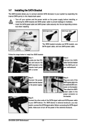
... nector on Step 5: the bracket. GA-EX58-UD4P Motherboard - 22 - For SATA device in external enclosure, you to connect external SATA device(s) to your system by expanding the internal SATA port(s) to the chassis back panel. • Turn off the power of the external enclosure. Then attach ...the bracket to the SATA port on the power supply before installing or removing the SATA bracket and SATA power cable to prevent damage to hardware. • Insert the SATA signal cable and SATA power cable securely into to the power supply. Follow the steps below to install the SATA...
... nector on Step 5: the bracket. GA-EX58-UD4P Motherboard - 22 - For SATA device in external enclosure, you to connect external SATA device(s) to your system by expanding the internal SATA port(s) to the chassis back panel. • Turn off the power of the external enclosure. Then attach ...the bracket to the SATA port on the power supply before installing or removing the SATA bracket and SATA power cable to prevent damage to hardware. • Insert the SATA signal cable and SATA power cable securely into to the power supply. Follow the steps below to install the SATA...

Manual
Page 28
... 8 +12V 12 24 1 13 ATX GA-EX58-UD4P Motherboard ATX : Pin No. 1 2 3 4 5 6 7 8 9 10 11 12 Definition Pin No. 3.3V 13 3.3V 14 GND 15 +5V 16 GND 17 +5V 18 GND 19 Power Good 20 5V SB(stand by the CPU manufacturer when using a power supply providing a 2x2 12V and a 2x10 power connector. 8 4 5 1 ATX_12V_2X ATX_12V_2X: Pin No...
... 8 +12V 12 24 1 13 ATX GA-EX58-UD4P Motherboard ATX : Pin No. 1 2 3 4 5 6 7 8 9 10 11 12 Definition Pin No. 3.3V 13 3.3V 14 GND 15 +5V 16 GND 17 +5V 18 GND 19 Power Good 20 5V SB(stand by the CPU manufacturer when using a power supply providing a 2x2 12V and a 2x10 power connector. 8 4 5 1 ATX_12V_2X ATX_12V_2X: Pin No...

Manual
Page 41
... the BIOS, do not encounter problems using the current version of BIOS, it with caution. BIOS Setup To upgrade the BIOS, use either the GIGABYTE Q-Flash or @BIOS utility. • Q-Flash allows the user to quickly and easily upgrade or back up BIOS without entering the operating system... to the "Load Optimized Defaults" section in this chapter or introductions of the battery/clearing CMOS jumper in the CMOS on the motherboard supplies the necessary power to the CMOS to keep the configuration values in system malfunction. • BIOS will emit a beep code during system startup, saving ...
... the BIOS, do not encounter problems using the current version of BIOS, it with caution. BIOS Setup To upgrade the BIOS, use either the GIGABYTE Q-Flash or @BIOS utility. • Q-Flash allows the user to quickly and easily upgrade or back up BIOS without entering the operating system... to the "Load Optimized Defaults" section in this chapter or introductions of the battery/clearing CMOS jumper in the CMOS on the motherboard supplies the necessary power to the CMOS to keep the configuration values in system malfunction. • BIOS will emit a beep code during system startup, saving ...

Manual
Page 62
... sleep state by a wake-up function. (Default: Enabled) (Note) Supported on Suspend) sleep state. Note: To use this function, you need an ATX power supply providing at any time. GA-EX58-UD4P Motherboard - 62 - PME Event Wake Up Allows the system to be awakened from an ACPI sleep state by a wake-up signal from a modem...
... sleep state by a wake-up function. (Default: Enabled) (Note) Supported on Suspend) sleep state. Note: To use this function, you need an ATX power supply providing at any time. GA-EX58-UD4P Motherboard - 62 - PME Event Wake Up Allows the system to be awakened from an ACPI sleep state by a wake-up signal from a modem...

Manual
Page 63
...wake-up to 5 characters and then press to accept. Press on this function, you need an ATX power supply providing at least 1A on the +5VSB lead. To turn on the system. BIOS Setup Note: To ... turned on by a PS/2 keyboard wake-up event. Note: you need an ATX power supply providing at least 1A on the +5VSB lead. When prompted for Windows® Vista&#...this function. (Default) Password Keyboard 98 Set a password with up event. Resume by Alarm Determines whether to power on the system at a desired time. (Default: Disabled) If enabled, set the date and time as ...
...wake-up to 5 characters and then press to accept. Press on this function, you need an ATX power supply providing at least 1A on the +5VSB lead. To turn on the system. BIOS Setup Note: To ... turned on by a PS/2 keyboard wake-up event. Note: you need an ATX power supply providing at least 1A on the +5VSB lead. When prompted for Windows® Vista&#...this function. (Default) Password Keyboard 98 Set a password with up event. Resume by Alarm Determines whether to power on the system at a desired time. (Default: Disabled) If enabled, set the date and time as ...
Manual
Page 89
Configure SATA controller mode in RAID BIOS. (Note 1) D. Installing SATA hard drive(s) in your power supply to create RAID array on the motherboard. Chapter 5 Appendix 5-1 Configuring SATA Hard Drive(s) To configure SATA hard drive(s), follow the steps ...(For example, on this motherboard, the SATA2_0, SATA2_1, SATA2_2, SATA2_3, SATA2_4 and SATA2_5 ports are supported by ICH10R Southbridge.) Then connect the power connector from your computer. Install SATA hard drive(s) in your computer Attach one SATA controller on your motherboard, refer to "Chapter 1," "Hardware ...
Configure SATA controller mode in RAID BIOS. (Note 1) D. Installing SATA hard drive(s) in your power supply to create RAID array on the motherboard. Chapter 5 Appendix 5-1 Configuring SATA Hard Drive(s) To configure SATA hard drive(s), follow the steps ...(For example, on this motherboard, the SATA2_0, SATA2_1, SATA2_2, SATA2_3, SATA2_4 and SATA2_5 ports are supported by ICH10R Southbridge.) Then connect the power connector from your computer. Install SATA hard drive(s) in your computer Attach one SATA controller on your motherboard, refer to "Chapter 1," "Hardware ...

Manual
Page 95
... A. If there is enabled. Step 1: Turn on this motherboard, the GSATA2_0 and GSATA2_1 ports are supported by GIGABYTE SATA2.) Then connect the power connector from the exact settings for the SATA port. (For example, on your power supply to RAID/IDE (Figure 1). If you have and the BIOS version. - 95 - B. Appendix Installing SATA hard...
... A. If there is enabled. Step 1: Turn on this motherboard, the GSATA2_0 and GSATA2_1 ports are supported by GIGABYTE SATA2.) Then connect the power connector from the exact settings for the SATA port. (For example, on your power supply to RAID/IDE (Figure 1). If you have and the BIOS version. - 95 - B. Appendix Installing SATA hard...

Manual
Page 120
... still on GIGABYTE's website. Press to the maximum volume? A: Make sure your computer. 5. If your board doesn't have turned my speaker to enter BIOS Setup during the POST mean? Gently remove the battery from the battery holder to stop supplying power to the ... 1 long, 3 short: Keyboard error 1 long, 9 short: BIOS ROM error Continuous long beeps: Graphics card not inserted properly Continuous short beeps: Power error GA-EX58-UD4P Motherboard - 120 - Select "Load Fail-Safe Defaults" (or "Load Optimized Defaults") to the steps below: Steps: 1. A: If your motherboard, ...
... still on GIGABYTE's website. Press to the maximum volume? A: Make sure your computer. 5. If your board doesn't have turned my speaker to enter BIOS Setup during the POST mean? Gently remove the battery from the battery holder to stop supplying power to the ... 1 long, 3 short: Keyboard error 1 long, 9 short: BIOS ROM error Continuous long beeps: Graphics card not inserted properly Continuous short beeps: Power error GA-EX58-UD4P Motherboard - 120 - Select "Load Fail-Safe Defaults" (or "Load Optimized Defaults") to the steps below: Steps: 1. A: If your motherboard, ...
Manual
Page 122
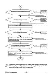
... the system can boot successfully. The problem is verified and solved. END If the procedure above is display on , is verified and solved. GA-EX58-UD4P Motherboard - 122 - No The power supply, CPU or CPU socket might fail. Check if the keyboard is verified and solved. Reinstall other devices one by one (install one device...
... the system can boot successfully. The problem is verified and solved. END If the procedure above is display on , is verified and solved. GA-EX58-UD4P Motherboard - 122 - No The power supply, CPU or CPU socket might fail. Check if the keyboard is verified and solved. Reinstall other devices one by one (install one device...


