Manual
Page 10
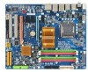
...® Pentium® Dual-Core processor/Intel® Celeron® processor in the LGA 775 package (Go to GIGABYTE's website for the latest CPU support list.) L2 cache varies with CPU 1600/1333/1066/800...61559; Support for DDR3 1900 (O.C.)/1600/1333/1066/800 MHz memory modules (Go to GIGABYTE's website for the latest memory support list.) Realtek ALC889A codec High Definition Audio 2/4/5.1/7.1-channel Support for Dolby® Home Theater (Note ... disk drive connector supporting up to the internal IEEE 1394a header) Only for GA-EP45T-DS3.
...® Pentium® Dual-Core processor/Intel® Celeron® processor in the LGA 775 package (Go to GIGABYTE's website for the latest CPU support list.) L2 cache varies with CPU 1600/1333/1066/800...61559; Support for DDR3 1900 (O.C.)/1600/1333/1066/800 MHz memory modules (Go to GIGABYTE's website for the latest memory support list.) Realtek ALC889A codec High Definition Audio 2/4/5.1/7.1-channel Support for Dolby® Home Theater (Note ... disk drive connector supporting up to the internal IEEE 1394a header) Only for GA-EP45T-DS3.
Manual
Page 23
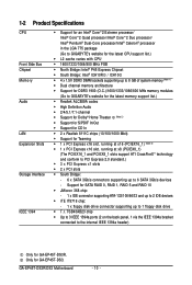
... on the motherboard. If a power supply is used that can withstand high power consumption be used (400W or greater). Definition 1 GND (Only for 2x4 pin 12V) 2 GND (Only for 2x4 pin 12V) 3 GND 4 GND 5 +...12V) 7 +12V 8 +12V 12 24 1 13 ATX ATX: Pin No. 1 2 3 4 5 6 7 8 9 10 11 12 Definition Pin No. 3.3V 13 3.3V 14 GND 15 +5V 16 GND 17 +5V 18 GND 19 Power Good 20 5V SB(stand by +5V...) 21 +12V 22 +12V(Onlyfor2x12-pinATX) 23 3.3V(Onlyfor2x12-pinATX) 24 Definition 3.3V -12V GND PS_ON(soft On/Off) GND GND GND -5V +5V +5V +5V (Only for...
... on the motherboard. If a power supply is used that can withstand high power consumption be used (400W or greater). Definition 1 GND (Only for 2x4 pin 12V) 2 GND (Only for 2x4 pin 12V) 3 GND 4 GND 5 +...12V) 7 +12V 8 +12V 12 24 1 13 ATX ATX: Pin No. 1 2 3 4 5 6 7 8 9 10 11 12 Definition Pin No. 3.3V 13 3.3V 14 GND 15 +5V 16 GND 17 +5V 18 GND 19 Power Good 20 5V SB(stand by +5V...) 21 +12V 22 +12V(Onlyfor2x12-pinATX) 23 3.3V(Onlyfor2x12-pinATX) 24 Definition 3.3V -12V GND PS_ON(soft On/Off) GND GND GND -5V +5V +5V +5V (Only for...

Manual
Page 24
The black connector wire is typically designated by a stripe of different color. 34 33 GA-EP45T-DS3R/DS3 Motherboard 2 1 - 24 - 3/4/5) CPU_FAN/SYS_FAN1/SYS_FAN2/PWR_FAN (Fan Headers) The motherboard has a 4-pin CPU fan header (CPU_FAN), a 3-pin (SYS_FAN1)...Before connecting a floppy disk drive, be installed inside the chassis. 1 CPU_FAN CPU_FAN: Pin No. 1 2 3 4 Definition GND +12V Sense Speed Control 1 SYS_FAN2 SYS_FAN2: Pin No. 1 2 3 4 Definition GND Speed Control Sense +5V 1 SYS_FAN1 1 PWR_FAN SYS_FAN1/PWR_FAN: Pin No. A red power connector wire indicates a positive...
The black connector wire is typically designated by a stripe of different color. 34 33 GA-EP45T-DS3R/DS3 Motherboard 2 1 - 24 - 3/4/5) CPU_FAN/SYS_FAN1/SYS_FAN2/PWR_FAN (Fan Headers) The motherboard has a 4-pin CPU fan header (CPU_FAN), a 3-pin (SYS_FAN1)...Before connecting a floppy disk drive, be installed inside the chassis. 1 CPU_FAN CPU_FAN: Pin No. 1 2 3 4 Definition GND +12V Sense Speed Control 1 SYS_FAN2 SYS_FAN2: Pin No. 1 2 3 4 Definition GND Speed Control Sense +5V 1 SYS_FAN1 1 PWR_FAN SYS_FAN1/PWR_FAN: Pin No. A red power connector wire indicates a positive...
Manual
Page 25
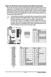
... to your SATA hard drive. Before attaching the IDE cable, locate the foolproof groove on the connector. SATA2_4 7 1 SATA2_5 SATA2_2 SATA2_3 SATA2_0 1 7 SATA2_1 Pin No. 1 2 3 4 5 6 7 Definition GND TXP TXN GND RXN RXP GND Only for the IDE devices, read the instructions from the device manufacturers.) 1 2 39 40 8) SATA2_0/1/2/3/4/5 (SATA 3Gb/s Connectors... a single SATA device. Please connect the L-shaped end of the IDE devices (for example, master or slave). (For information about configuring master/slave settings for GA-EP45T-DS3. - 25 -
... to your SATA hard drive. Before attaching the IDE cable, locate the foolproof groove on the connector. SATA2_4 7 1 SATA2_5 SATA2_2 SATA2_3 SATA2_0 1 7 SATA2_1 Pin No. 1 2 3 4 5 6 7 Definition GND TXP TXN GND RXN RXP GND Only for the IDE devices, read the instructions from the device manufacturers.) 1 2 39 40 8) SATA2_0/1/2/3/4/5 (SATA 3Gb/s Connectors... a single SATA device. Please connect the L-shaped end of the IDE devices (for example, master or slave). (For information about configuring master/slave settings for GA-EP45T-DS3. - 25 -

Manual
Page 26
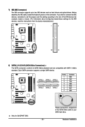
...at least four hard drives and the total number of the SATA 3Gb/s cable to Chapter 5, "Configuring SATA Hard Drive(s)," for GA-EP45T-DS3R. Each SATA connector supports a single SATA device. Definition 1 GND 2 TXP SATA2_4 SATA2_2 SATA2_0 3 TXN 7 4 GND 1 SATA2_5 SATA2_3 SATA2_1 5 RXN 6 RXP 7 GND Please ...of hard drives does not have to be used to connect a system power LED on the chassis to indicate system power status. GA-EP45T-DS3R/DS3 Motherboard - 26 - Pin No. The LED keeps blinking when the system is in S1 sleep state. The LED is on configuring a...
...at least four hard drives and the total number of the SATA 3Gb/s cable to Chapter 5, "Configuring SATA Hard Drive(s)," for GA-EP45T-DS3R. Each SATA connector supports a single SATA device. Definition 1 GND 2 TXP SATA2_4 SATA2_2 SATA2_0 3 TXN 7 4 GND 1 SATA2_5 SATA2_3 SATA2_1 5 RXN 6 RXP 7 GND Please ...of hard drives does not have to be used to connect a system power LED on the chassis to indicate system power status. GA-EP45T-DS3R/DS3 Motherboard - 26 - Pin No. The LED keeps blinking when the system is in S1 sleep state. The LED is on configuring a...

Manual
Page 28
... 6 NC 7 FAUDIO_JD 7 NC 8 No Pin 8 No Pin 9 LINE2_L 9 Line Out (L) 10 GND 10 NC • The front panel audio header supports HD audio by default. Definition 1 CD-L 2 GND 3 GND 4 CD-R 1 GA-EP45T-DS3R/DS3 Motherboard - 28 - 11) F_AUDIO (Front Panel Audio Header) The front panel audio header supports Intel High...
... 6 NC 7 FAUDIO_JD 7 NC 8 No Pin 8 No Pin 9 LINE2_L 9 Line Out (L) 10 GND 10 NC • The front panel audio header supports HD audio by default. Definition 1 CD-L 2 GND 3 GND 4 CD-R 1 GA-EP45T-DS3R/DS3 Motherboard - 28 - 11) F_AUDIO (Front Panel Audio Header) The front panel audio header supports Intel High...
Manual
Page 29
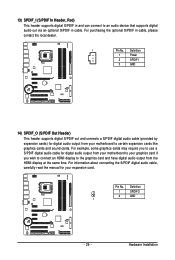
... to the graphics card and have digital audio output from the HDMI display at the same time. Definition 1 SPDIFO 2 GND 1 - 29 - For purchasing the optional S/PDIF in cable, please contact the local dealer. 1 Pin No. Definition 1 Power 2 SPDIFI 3 GND 14) SPDIF_O (S/PDIF Out Header) This header supports digital S/PDIF out and connects...
... to the graphics card and have digital audio output from the HDMI display at the same time. Definition 1 SPDIFO 2 GND 1 - 29 - For purchasing the optional S/PDIF in cable, please contact the local dealer. 1 Pin No. Definition 1 Power 2 SPDIFI 3 GND 14) SPDIF_O (S/PDIF Out Header) This header supports digital S/PDIF out and connects...

Manual
Page 30
... IEEE 1394a header can provide two USB ports via an optional IEEE 1394a bracket. GA-EP45T-DS3R/DS3 Motherboard - 30 - For purchasing the optional IEEE 1394a bracket, please contact the local dealer. 9 1 10 2 Pin No. 1 2 3 4 5 6 7 8 9 10 Definition TPA+ TPAGND GND TPB+ TPBPower (12V) Power (12V) No Pin GND ... IEEE 1394a specification. For purchasing the optional USB bracket, please contact the local dealer. 10 9 2 1 Pin No. 1 2 3 4 5 6 7 8 9 10 Definition Power (5V) Power (5V) USB DXUSB DYUSB DX+ USB DY+ GND GND No Pin NC • Do not plug the IEEE 1394 bracket (2x5-pin...
... IEEE 1394a header can provide two USB ports via an optional IEEE 1394a bracket. GA-EP45T-DS3R/DS3 Motherboard - 30 - For purchasing the optional IEEE 1394a bracket, please contact the local dealer. 9 1 10 2 Pin No. 1 2 3 4 5 6 7 8 9 10 Definition TPA+ TPAGND GND TPB+ TPBPower (12V) Power (12V) No Pin GND ... IEEE 1394a specification. For purchasing the optional USB bracket, please contact the local dealer. 10 9 2 1 Pin No. 1 2 3 4 5 6 7 8 9 10 Definition Power (5V) Power (5V) USB DXUSB DYUSB DX+ USB DY+ GND GND No Pin NC • Do not plug the IEEE 1394 bracket (2x5-pin...
Manual
Page 31
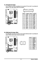
...LPT port cable, please contact the local dealer. 25 1 26 Pin No. 1 2 3 4 5 6 7 8 9 10 11 12 13 2 Definition STBAFDPD0 ERRPD1 INITPD2 SLINPD3 GND PD4 GND PD5 Pin No. 14 15 16 17 18 19 20 21 22 23 24 25 26... Definition GND PD6 GND PD7 GND ACKGND BUSY GND PE No Pin SLCT GND 18) COMA (Serial Port Header, ... purchasing the optional COM port cable, please contact the local dealer. 9 1 10 2 Pin No. 1 2 3 4 5 6 7 8 9 10 Definition NDCD ANSIN A NSOUT A NDTR AGND NDSR ANRTS ANCTS ANRI ANo Pin - 31 - Hardware Installation
...LPT port cable, please contact the local dealer. 25 1 26 Pin No. 1 2 3 4 5 6 7 8 9 10 11 12 13 2 Definition STBAFDPD0 ERRPD1 INITPD2 SLINPD3 GND PD4 GND PD5 Pin No. 14 15 16 17 18 19 20 21 22 23 24 25 26... Definition GND PD6 GND PD7 GND ACKGND BUSY GND PE No Pin SLCT GND 18) COMA (Serial Port Header, ... purchasing the optional COM port cable, please contact the local dealer. 9 1 10 2 Pin No. 1 2 3 4 5 6 7 8 9 10 Definition NDCD ANSIN A NSOUT A NDTR AGND NDSR ANRTS ANCTS ANRI ANo Pin - 31 - Hardware Installation

Manual
Page 32
... pins for BIOS configurations). GA-EP45T-DS3R/DS3 Motherboard - 32 - To clear the CMOS values, place a jumper cap on your computer and unplug the power cord from the jumper. 19) CI (Chassis Intrusion Header) This motherboard provides a chassis detection feature that detects if the chassis cover has been removed. Definition 1 Signal 1 2 GND 20) CLR_CMOS...
... pins for BIOS configurations). GA-EP45T-DS3R/DS3 Motherboard - 32 - To clear the CMOS values, place a jumper cap on your computer and unplug the power cord from the jumper. 19) CI (Chassis Intrusion Header) This motherboard provides a chassis detection feature that detects if the chassis cover has been removed. Definition 1 Signal 1 2 GND 20) CLR_CMOS...
Manual
Page 98
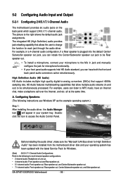
... Control Panel. Configuring Speakers: (The following for High Definition Audio" has been installed from the motherboard driver disk and your system tray. Doubleclick the icon to the right shows the default audio jack assignments. GA-EP45T-DS3R/DS3 Motherboard - 98 - 5-2 Configuring Audio Input and Output...out. • 7.1-channel audio: Front speaker out, Rear speaker out, Center/Subwoofer speaker out, and Side speaker out. High Definition Audio (HD Audio) HD Audio includes multiple high quality digital-to-analog converters (DACs) that allows the user to the following ...
... Control Panel. Configuring Speakers: (The following for High Definition Audio" has been installed from the motherboard driver disk and your system tray. Doubleclick the icon to the right shows the default audio jack assignments. GA-EP45T-DS3R/DS3 Motherboard - 98 - 5-2 Configuring Audio Input and Output...out. • 7.1-channel audio: Front speaker out, Rear speaker out, Center/Subwoofer speaker out, and Side speaker out. High Definition Audio (HD Audio) HD Audio includes multiple high quality digital-to-analog converters (DACs) that allows the user to the following ...
