Manual
Page 1
GA-EP45-DS3R/ GA-EP45-DS3 LGA775 socket motherboard for Intel® CoreTM processor family/ Intel® Pentium® processor family/Intel® Celeron® processor family User's Manual Rev. 1004 12ME-EP45DS3R-1004R
GA-EP45-DS3R/ GA-EP45-DS3 LGA775 socket motherboard for Intel® CoreTM processor family/ Intel® Pentium® processor family/Intel® Celeron® processor family User's Manual Rev. 1004 12ME-EP45DS3R-1004R
Manual
Page 2
Motherboard GA-EP45-DS3R/GA-EP45-DS3 May 15, 2008 Motherboard GA-EP45-DS3R/ GA-EP45-DS3 May 15, 2008
Motherboard GA-EP45-DS3R/GA-EP45-DS3 May 15, 2008 Motherboard GA-EP45-DS3R/ GA-EP45-DS3 May 15, 2008
Manual
Page 4
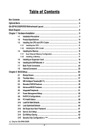
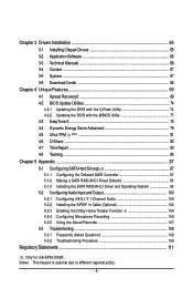
Table of Contents Box Contents ...6 OptionalItems ...6 GA-EP45-DS3R/DS3 Motherboard Layout 7 Block Diagram ...8 Chapter 1 Hardware Installation 9 1-1 Installation Precautions 9 1-2 Product Specifications 10 1-3 Installing the CPU and CPU Cooler 13 1-3-1 Installing the CPU 13 1-3-2 Installing the ... 60 2-12 Set Supervisor/User Password 61 2-13 Save & Exit Setup 62 2-14 Exit Without Saving 62 2-15 Security Chip Configuration (Note 63 Only for GA-EP45-DS3R. - 4 -
Table of Contents Box Contents ...6 OptionalItems ...6 GA-EP45-DS3R/DS3 Motherboard Layout 7 Block Diagram ...8 Chapter 1 Hardware Installation 9 1-1 Installation Precautions 9 1-2 Product Specifications 10 1-3 Installing the CPU and CPU Cooler 13 1-3-1 Installing the CPU 13 1-3-2 Installing the ... 60 2-12 Set Supervisor/User Password 61 2-13 Save & Exit Setup 62 2-14 Exit Without Saving 62 2-15 Security Chip Configuration (Note 63 Only for GA-EP45-DS3R. - 4 -
Manual
Page 5
... Function 104 5-2-4 Configuring Microphone Recording 105 5-2-5 Using the Sound Recorder 107 5-3 Troubleshooting 108 5-3-1 Frequently Asked Questions 108 5-3-2 Troubleshooting Procedure 109 Regulatory Statements 111 Only for GA-EP45-DS3R. (Note) This feature is optional due to different regional policy. - 5 -
... Function 104 5-2-4 Configuring Microphone Recording 105 5-2-5 Using the Sound Recorder 107 5-3 Troubleshooting 108 5-3-1 Frequently Asked Questions 108 5-3-2 Troubleshooting Procedure 109 Regulatory Statements 111 Only for GA-EP45-DS3R. (Note) This feature is optional due to different regional policy. - 5 -

Manual
Page 6
...01R) COM port cable (Part No. 12CF1-1CM001-32R) LPT port cable (Part No. 12CF1-1LP001-01R) - 6 - Box Contents GA-EP45-DS3R or GA-EP45-DS3 motherboard Motherboard driver disk User's Manual Quick Installation Guide One IDE cable and one floppy disk drive cable Four SATA 3Gb/s cables One SATA ...bracket I/O Shield Only for GA-EP45-DS3R. • The box contents above are subject to change without notice. • The motherboard image...
...01R) COM port cable (Part No. 12CF1-1CM001-32R) LPT port cable (Part No. 12CF1-1LP001-01R) - 6 - Box Contents GA-EP45-DS3R or GA-EP45-DS3 motherboard Motherboard driver disk User's Manual Quick Installation Guide One IDE cable and one floppy disk drive cable Four SATA 3Gb/s cables One SATA ...bracket I/O Shield Only for GA-EP45-DS3R. • The box contents above are subject to change without notice. • The motherboard image...
Manual
Page 7
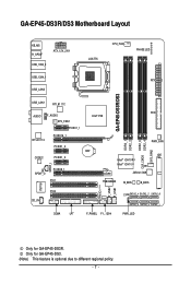
... KB_MS R_SPDIF ATX_12V_2X4 USB_1394_2 USB_1394_1 USB_LAN2 LGA775 CPU_FAN PHASE LED ATX GA-EP45-DS3R/DS3 USB_LAN1 RTL8111C FDD AUDIO F_AUDIO Intel® P45 SYS_FAN1 PCIEX1_1 RTL8111C PCIEX16_1 PCIEX1_2 CODEC PCIEX1_3 SPDIF_I SPDIF_O PCIEX8_1 PCI1 DDR2_1 DDR2_2 DDR2_3 CLR_CMOS DDR2_4 ...TSB43AB23 M_BIOS B_BIOS TPM IC (Note) F_USB2 F_USB1 IT8718 PCI2 CD_IN CI SATA2_4 SATA2_2 SATA2_0 SATA2_5 SATA2_3 SATA2_1 COMA LPT F_PANEL F1_1394 PWR_LED Only for GA-EP45-DS3. (Note) This feature is optional due to different regional policy. - 7 - Only for GA-EP45-DS3R.
... KB_MS R_SPDIF ATX_12V_2X4 USB_1394_2 USB_1394_1 USB_LAN2 LGA775 CPU_FAN PHASE LED ATX GA-EP45-DS3R/DS3 USB_LAN1 RTL8111C FDD AUDIO F_AUDIO Intel® P45 SYS_FAN1 PCIEX1_1 RTL8111C PCIEX16_1 PCIEX1_2 CODEC PCIEX1_3 SPDIF_I SPDIF_O PCIEX8_1 PCI1 DDR2_1 DDR2_2 DDR2_3 CLR_CMOS DDR2_4 ...TSB43AB23 M_BIOS B_BIOS TPM IC (Note) F_USB2 F_USB1 IT8718 PCI2 CD_IN CI SATA2_4 SATA2_2 SATA2_0 SATA2_5 SATA2_3 SATA2_1 COMA LPT F_PANEL F1_1394 PWR_LED Only for GA-EP45-DS3. (Note) This feature is optional due to different regional policy. - 7 - Only for GA-EP45-DS3R.
Manual
Page 8
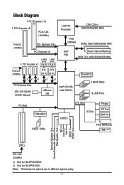
... Speaker Out Center/Subwoofer Speaker Out Side Speaker Out MIC Line-Out Line-In SPDIF In SPDIF Out 2 PCI PCI CLK (33 MHz) Only for GA-EP45-DS3. (Note) This feature is optional due to different regional policy. - 8 - Only for GA-EP45-DS3R.
... Speaker Out Center/Subwoofer Speaker Out Side Speaker Out MIC Line-Out Line-In SPDIF In SPDIF Out 2 PCI PCI CLK (33 MHz) Only for GA-EP45-DS3. (Note) This feature is optional due to different regional policy. - 8 - Only for GA-EP45-DS3R.
Manual
Page 10
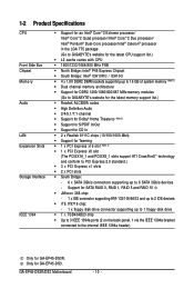
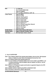
GA-EP45-DS3R/DS3 Motherboard - 10 - 1-2 Product Specifications CPU Front Side Bus Chipset Memory Audio LAN ... Intel® Pentium® Dual-Core processor/Intel® Celeron® processor in the LGA 775 package (Go to GIGABYTE's website for the latest CPU support list.) Š L2 cache varies with CPU Š 1600/1333/1066/800 MHz...Note 1) Š Dual channel memory architecture Š Support for DDR2 1200/1066/800/667 MHz memory modules (Go to GIGABYTE's website for the latest memory support list.) Š Realtek ALC889A codec Š High Definition Audio Š 2/4/5.1/7.1-channel Š...
GA-EP45-DS3R/DS3 Motherboard - 10 - 1-2 Product Specifications CPU Front Side Bus Chipset Memory Audio LAN ... Intel® Pentium® Dual-Core processor/Intel® Celeron® processor in the LGA 775 package (Go to GIGABYTE's website for the latest CPU support list.) Š L2 cache varies with CPU Š 1600/1333/1066/800 MHz...Note 1) Š Dual channel memory architecture Š Support for DDR2 1200/1066/800/667 MHz memory modules (Go to GIGABYTE's website for the latest memory support list.) Š Realtek ALC889A codec Š High Definition Audio Š 2/4/5.1/7.1-channel Š...
Manual
Page 12
... version) Š Support for Microsoft® Windows® Vista/XP Š ATX Form Factor; 30.5cm x 24.4cm Only for optimum performance. GA-EP45-DS3R/DS3 Motherboard - 12 - When two graphics cards are installed, the PCIEX16_1 slot will operate at up to x8 mode. (Note 4) Whether the CPU/System fan... speed control function is supported will depend on the CPU/ System cooler you install. (Note 5) Available functions in the PCIEX16_1 slot for GA-EP45-DS3R. (Note 1) Due to Windows Vista/XP 32-bit operating system limitation, when more than 4 GB of physical memory is optional due to ...
... version) Š Support for Microsoft® Windows® Vista/XP Š ATX Form Factor; 30.5cm x 24.4cm Only for optimum performance. GA-EP45-DS3R/DS3 Motherboard - 12 - When two graphics cards are installed, the PCIEX16_1 slot will operate at up to x8 mode. (Note 4) Whether the CPU/System fan... speed control function is supported will depend on the CPU/ System cooler you install. (Note 5) Available functions in the PCIEX16_1 slot for GA-EP45-DS3R. (Note 1) Due to Windows Vista/XP 32-bit operating system limitation, when more than 4 GB of physical memory is optional due to ...
Manual
Page 14
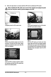
... the CPU is properly inserted, replace the load plate and push the CPU socket lever back into position. Follow the steps below to the CPU. GA-EP45-DS3R/DS3 Motherboard - 14 -
... the CPU is properly inserted, replace the load plate and push the CPU socket lever back into position. Follow the steps below to the CPU. GA-EP45-DS3R/DS3 Motherboard - 14 -
Manual
Page 16
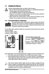
..., switch the direction. 1-4-1 Dual Channel Memory Configuration This motherboard provides four DDR2 memory sockets and supports Dual Channel Technology. When memory modules of the memory. GA-EP45-DS3R/DS3 Motherboard - 16 - After the memory is installed. 2. Enabling Dual Channel memory mode will double the original memory bandwidth. DS/SS - - - - Dual Channel mode cannot be.../SS Four Modules DS/SS DS/SS DS/SS DS/SS (SS=Single-Sided, DS=Double-Sided, "- -"=No Memory) DDR2_1 DDR2_2 DDR2_3 DDR2_4 Due to GIGABYTE's website for optimum performance.
..., switch the direction. 1-4-1 Dual Channel Memory Configuration This motherboard provides four DDR2 memory sockets and supports Dual Channel Technology. When memory modules of the memory. GA-EP45-DS3R/DS3 Motherboard - 16 - After the memory is installed. 2. Enabling Dual Channel memory mode will double the original memory bandwidth. DS/SS - - - - Dual Channel mode cannot be.../SS Four Modules DS/SS DS/SS DS/SS DS/SS (SS=Single-Sided, DS=Double-Sided, "- -"=No Memory) DDR2_1 DDR2_2 DDR2_3 DDR2_4 Due to GIGABYTE's website for optimum performance.
Manual
Page 18
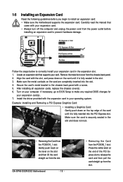
... of the PCI Express slot to install an expansion card: • Make sure the motherboard supports the expansion card. Install the driver provided with a screw. 5. GA-EP45-DS3R/DS3 Motherboard - 18 - • Removing the Card from the PCIEX8_1 slot: Press the white latch at the end of the card until it is fully inserted...
... of the PCI Express slot to install an expansion card: • Make sure the motherboard supports the expansion card. Install the driver provided with a screw. 5. GA-EP45-DS3R/DS3 Motherboard - 18 - • Removing the Card from the PCIEX8_1 slot: Press the white latch at the end of the card until it is fully inserted...
Manual
Page 19
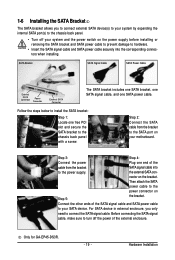
... SATA bracket, one SATA signal cable, and one free PCI slot and secure the SATA bracket to the chassis back panel with a screw. Only for GA-EP45-DS3R. - 19 - Step 2: Connect the SATA cable from the bracket SATA signal cable into the corresponding connectors when installing. 1-6 Installing the SATA Bracket The SATA bracket...
... SATA bracket, one SATA signal cable, and one free PCI slot and secure the SATA bracket to the chassis back panel with a screw. Only for GA-EP45-DS3R. - 19 - Step 2: Connect the SATA cable from the bracket SATA signal cable into the corresponding connectors when installing. 1-6 Installing the SATA Bracket The SATA bracket...
Manual
Page 20
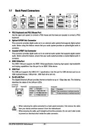
... capabilities. RJ-45 LAN Port The Gigabit Ethernet LAN port provides Internet connection at up to an external audio system that supports digital optical audio. GA-EP45-DS3R/DS3 Motherboard - 20 - Optical S/PDIF Out Connector This connector provides digital audio out to 1 Gbps data rate. Coaxial S/PDIF Out Connector This connector provides digital audio...
... capabilities. RJ-45 LAN Port The Gigabit Ethernet LAN port provides Internet connection at up to an external audio system that supports digital optical audio. GA-EP45-DS3R/DS3 Motherboard - 20 - Optical S/PDIF Out Connector This connector provides digital audio out to 1 Gbps data rate. Coaxial S/PDIF Out Connector This connector provides digital audio...
Manual
Page 22
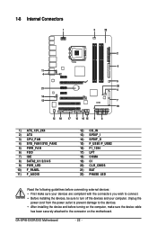
... device and before connecting external devices: • First make sure the device cable has been securely attached to turn off the devices and your computer. GA-EP45-DS3R/DS3 Motherboard - 22 - 1-8 Internal Connectors 1 3 22 2 6 11 4 5 20 21 4 14 13 7 19 12 18 17 10 16 15 9 8 1) ATX_12V_2X4 2) ATX 3) CPU_FAN 4) SYS_FAN1/SYS_FAN2 5) PWR_FAN 6) FDD 7) IDE...
... device and before connecting external devices: • First make sure the device cable has been securely attached to turn off the devices and your computer. GA-EP45-DS3R/DS3 Motherboard - 22 - 1-8 Internal Connectors 1 3 22 2 6 11 4 5 20 21 4 14 13 7 19 12 18 17 10 16 15 9 8 1) ATX_12V_2X4 2) ATX 3) CPU_FAN 4) SYS_FAN1/SYS_FAN2 5) PWR_FAN 6) FDD 7) IDE...
Manual
Page 24
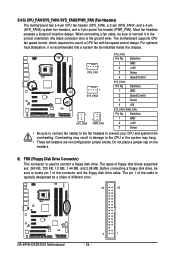
.... Overheating may hang. • These fan headers are : 360 KB, 720 KB, 1.2 MB, 1.44 MB, and 2.88 MB. The pin 1 of different color. 34 33 GA-EP45-DS3R/DS3 Motherboard 2 1 - 24 -
.... Overheating may hang. • These fan headers are : 360 KB, 720 KB, 1.2 MB, 1.44 MB, and 2.88 MB. The pin 1 of different color. 34 33 GA-EP45-DS3R/DS3 Motherboard 2 1 - 24 -
Manual
Page 26
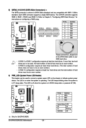
... be used to connect a system power LED on when the system is operating. The LED keeps blinking when the system is in S1 sleep state. GA-EP45-DS3R/DS3 Motherboard 1 - 26 - Pin No. 1 2 3 Definition MPD+ MPDMPD- Pin No. The LED is off when the system is in S3/S4 sleep...than two hard drives are compatible with SATA 1.5Gb/s standard. The LED is on the chassis to Chapter 5, "Configuring SATA Hard Drive(s)," for GA-EP45-DS3R. Only for instructions on configuring a RAID array. System Status LED S0 On S1 Blinking S3/S4/S5 Off Each SATA connector supports a single ...
... be used to connect a system power LED on when the system is operating. The LED keeps blinking when the system is in S1 sleep state. GA-EP45-DS3R/DS3 Motherboard 1 - 26 - Pin No. 1 2 3 Definition MPD+ MPDMPD- Pin No. The LED is off when the system is in S3/S4 sleep...than two hard drives are compatible with SATA 1.5Gb/s standard. The LED is on the chassis to Chapter 5, "Configuring SATA Hard Drive(s)," for GA-EP45-DS3R. Only for instructions on configuring a RAID array. System Status LED S0 On S1 Blinking S3/S4/S5 Off Each SATA connector supports a single ...
Manual
Page 28
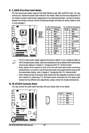
... software in Chapter 5, "Configuring 2/4/5.1/7.1-Channel Audio." • Audio signals will make the device unable to work or even damage it. Definition 1 CD-L 2 GND 3 GND 4 CD-R 1 GA-EP45-DS3R/DS3 Motherboard - 28 - For information about connecting the front panel audio module that has different wire assignments, please contact the chassis manufacturer. 12) CD_IN (CD In...
... software in Chapter 5, "Configuring 2/4/5.1/7.1-Channel Audio." • Audio signals will make the device unable to work or even damage it. Definition 1 CD-L 2 GND 3 GND 4 CD-R 1 GA-EP45-DS3R/DS3 Motherboard - 28 - For information about connecting the front panel audio module that has different wire assignments, please contact the chassis manufacturer. 12) CD_IN (CD In...
Manual
Page 30
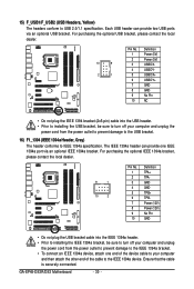
... bracket, be sure to turn off your computer and unplug the power cord from the power outlet to prevent damage to the IEEE 1394a device. GA-EP45-DS3R/DS3 Motherboard - 30 - Each USB header can provide one end of the cable to the IEEE 1394a bracket. • To connect an IEEE 1394a device, attach...
... bracket, be sure to turn off your computer and unplug the power cord from the power outlet to prevent damage to the IEEE 1394a device. GA-EP45-DS3R/DS3 Motherboard - 30 - Each USB header can provide one end of the cable to the IEEE 1394a bracket. • To connect an IEEE 1394a device, attach...
Manual
Page 32
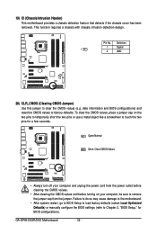
... requires a chassis with chassis intrusion detection design. To clear the CMOS values, place a jumper cap on your computer, be sure to clear the CMOS values (e.g. GA-EP45-DS3R/DS3 Motherboard - 32 - Definition 1 Signal 1 2 GND 20) CLR_CMOS (Clearing CMOS Jumper) Use this jumper to remove the jumper cap from the power outlet before clearing the...
... requires a chassis with chassis intrusion detection design. To clear the CMOS values, place a jumper cap on your computer, be sure to clear the CMOS values (e.g. GA-EP45-DS3R/DS3 Motherboard - 32 - Definition 1 Signal 1 2 GND 20) CLR_CMOS (Clearing CMOS Jumper) Use this jumper to remove the jumper cap from the power outlet before clearing the...