Manual
Page 1
GA-EP35-DS3R/ GA-EP35-DS3 LGA775 socket motherboard for Intel® CoreTM processor family/ Intel® Pentium® processor family/Intel® Celeron® processor family User's Manual Rev. 2101 12ME-EP35DS3R-2101R
GA-EP35-DS3R/ GA-EP35-DS3 LGA775 socket motherboard for Intel® CoreTM processor family/ Intel® Pentium® processor family/Intel® Celeron® processor family User's Manual Rev. 2101 12ME-EP35DS3R-2101R
Manual
Page 2
Motherboard GA-EP35-DS3R/DS3 Dec. 21, 2007 Motherboard GA-EP35-DS3R/DS3 Dec. 21, 2007
Motherboard GA-EP35-DS3R/DS3 Dec. 21, 2007 Motherboard GA-EP35-DS3R/DS3 Dec. 21, 2007

Manual
Page 4
Table of Contents Box Contents ...6 OptionalItems ...6 GA-EP35-DS3R/DS3 Motherboard Layout 7 Block Diagram ...8 Chapter 1 Hardware Installation 9 1-1 Installation Precautions 9 1-2 Product Specifications 10 1-3 Installing the CPU and CPU Cooler 13 1-3-1 Installing the CPU 13 1-3-2 Installing the ...
Table of Contents Box Contents ...6 OptionalItems ...6 GA-EP35-DS3R/DS3 Motherboard Layout 7 Block Diagram ...8 Chapter 1 Hardware Installation 9 1-1 Installation Precautions 9 1-2 Product Specifications 10 1-3 Installing the CPU and CPU Cooler 13 1-3-1 Installing the CPU 13 1-3-2 Installing the ...

Manual
Page 5
...Saver 74 4-5 Windows Vista ReadyBoost 76 Chapter 5 Appendix ...77 5-1 Configuring SATA Hard Drive(s 77 5-1-1 Configuring Intel® ICH9R SATA Controllers 77 5-1-2 Configuring GIGABYTE SATA2 SATA Controller 83 5-1-3 Making a SATA RAID/AHCI Driver Diskette 89 5-1-4 Installing the SATA RAID/AHCI Driver and Operating System 90 5-2 ConfiguringAudio Input and Output...Configuring Microphone Recording 102 5-2-4 Using the Sound Recorder 104 5-3 Troubleshooting 105 5-3-1 Frequently Asked Questions 105 5-3-2 Troubleshooting Procedure 106 Regulatory Statements 108 Only for GA-EP35-DS3R. - 5 -
...Saver 74 4-5 Windows Vista ReadyBoost 76 Chapter 5 Appendix ...77 5-1 Configuring SATA Hard Drive(s 77 5-1-1 Configuring Intel® ICH9R SATA Controllers 77 5-1-2 Configuring GIGABYTE SATA2 SATA Controller 83 5-1-3 Making a SATA RAID/AHCI Driver Diskette 89 5-1-4 Installing the SATA RAID/AHCI Driver and Operating System 90 5-2 ConfiguringAudio Input and Output...Configuring Microphone Recording 102 5-2-4 Using the Sound Recorder 104 5-3 Troubleshooting 105 5-3-1 Frequently Asked Questions 105 5-3-2 Troubleshooting Procedure 106 Regulatory Statements 108 Only for GA-EP35-DS3R. - 5 -
Manual
Page 6
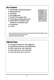
...01R) COM port cable (Part No. 12CF1-1CM001-32R) LPT port cable (Part No. 12CF1-1LP001-01R) - 6 - Box Contents GA-EP35-DS3R or GA-EP35-DS3 motherboard Motherboard driver disk User's Manual Quick Installation Guide Intel® LGA775 CPU Installation Guide One IDE cable and one floppy disk drive cable... GA-EP35-DS3R: Four SATA 3Gb/s cables GA-EP35-DS3: Two SATA 3Gb/s cables One SATA bracket I/O Shield • The box contents above are subject to change without notice...
...01R) COM port cable (Part No. 12CF1-1CM001-32R) LPT port cable (Part No. 12CF1-1LP001-01R) - 6 - Box Contents GA-EP35-DS3R or GA-EP35-DS3 motherboard Motherboard driver disk User's Manual Quick Installation Guide Intel® LGA775 CPU Installation Guide One IDE cable and one floppy disk drive cable... GA-EP35-DS3R: Four SATA 3Gb/s cables GA-EP35-DS3: Two SATA 3Gb/s cables One SATA bracket I/O Shield • The box contents above are subject to change without notice...
Manual
Page 7
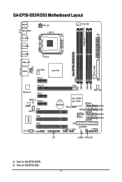
Only for GA-EP35-DS3R. GA-EP35-DS3R/DS3 Motherboard Layout KB_MS RCA_SPDIF R_USB1 R_USB2 R_USB3 ATX_12V LGA775 PHASE LED CPU_FAN ATX GA-EP35-DS3R/DS3 DDRII1 USB_LAN F_AUDIO AUDIO SYS_FAN1 PCIE_3 PCIE_16 RTL8111B PCIE_1 SPDIF_O PCIE_2 CODEC PCI1 SPDIF_I PCI2 IT8718 CD_IN PCI3 COMA Intel® P35 FDD DDRII3 DDRII4 DDRII2 PWR_FAN BATTERY Intel® ICH9R Intel® ICH9 SATAII2 CLR_CMOS SATAII3 GSATAII0 GIGABYTE SATA2 GSATAII1 SATAII0 SATAII1 SATAII4 SATAII5 IDE1 F_USB2 F_USB1 M_BIOS CI F_PANEL LPT B_BIOS PWR_LED SYS_FAN2 Only for GA-EP35-DS3. - 7 -
Only for GA-EP35-DS3R. GA-EP35-DS3R/DS3 Motherboard Layout KB_MS RCA_SPDIF R_USB1 R_USB2 R_USB3 ATX_12V LGA775 PHASE LED CPU_FAN ATX GA-EP35-DS3R/DS3 DDRII1 USB_LAN F_AUDIO AUDIO SYS_FAN1 PCIE_3 PCIE_16 RTL8111B PCIE_1 SPDIF_O PCIE_2 CODEC PCI1 SPDIF_I PCI2 IT8718 CD_IN PCI3 COMA Intel® P35 FDD DDRII3 DDRII4 DDRII2 PWR_FAN BATTERY Intel® ICH9R Intel® ICH9 SATAII2 CLR_CMOS SATAII3 GSATAII0 GIGABYTE SATA2 GSATAII1 SATAII0 SATAII1 SATAII4 SATAII5 IDE1 F_USB2 F_USB1 M_BIOS CI F_PANEL LPT B_BIOS PWR_LED SYS_FAN2 Only for GA-EP35-DS3. - 7 -
Manual
Page 8
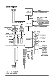
...+/(400(O.C.)/333/266/200 MHz) Host Interface DDR2 1200(O.C.)/1066/ 800/667 MHz PCI Express x16 2 SATA 3Gb/s ATA-133/100/66/33 IDE Channel GIGABYTE SATA2 LAN RJ45 RTL 8111B x1 PCI Express Bus x1 3 PCI Express x1 x 1 x 1 x 1 PCIe CLK (100 MHz) PCI Bus Intel® P35 Intel® ICH9R... Speaker Out Center/Subwoofer Speaker Out Side Speaker Out MIC Line-Out Line-In SPDIF In SPDIF Out 3 PCI PCI CLK (33 MHz) Only for GA-EP35-DS3. - 8 - Only for GA-EP35-DS3R.
...+/(400(O.C.)/333/266/200 MHz) Host Interface DDR2 1200(O.C.)/1066/ 800/667 MHz PCI Express x16 2 SATA 3Gb/s ATA-133/100/66/33 IDE Channel GIGABYTE SATA2 LAN RJ45 RTL 8111B x1 PCI Express Bus x1 3 PCI Express x1 x 1 x 1 x 1 PCIe CLK (100 MHz) PCI Bus Intel® P35 Intel® ICH9R... Speaker Out Center/Subwoofer Speaker Out Side Speaker Out MIC Line-Out Line-In SPDIF In SPDIF Out 3 PCI PCI CLK (33 MHz) Only for GA-EP35-DS3. - 8 - Only for GA-EP35-DS3R.
Manual
Page 10
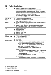
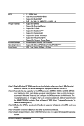
Support for GA-EP35-DS3R. GA-EP35-DS3R/DS3 Motherboard - 10 - Support for SATA RAID 0, RAID 1, RAID 5, and RAID 10 Š GIGABYTE SATA2 chip: - 1 x IDE connector supporting ATA-133/100/66/33 and up to 2 IDE devices - 2 x SATA 3Gb/s connectors (GSATAII0, GSATAII1)...(Note 1) Š Dual channel memory architecture Š Support for DDR2 1200(O.C.)/1066/800/667 MHz memory modules (Go to GIGABYTE's website for the latest memory support list.) Š Realtek ALC889A codec Š High Definition Audio Š 2/4/5.1/7.1-channel Š Support for S/PDIF In/Out Š Support for GA-EP35-DS3.
Support for GA-EP35-DS3R. GA-EP35-DS3R/DS3 Motherboard - 10 - Support for SATA RAID 0, RAID 1, RAID 5, and RAID 10 Š GIGABYTE SATA2 chip: - 1 x IDE connector supporting ATA-133/100/66/33 and up to 2 IDE devices - 2 x SATA 3Gb/s connectors (GSATAII0, GSATAII1)...(Note 1) Š Dual channel memory architecture Š Support for DDR2 1200(O.C.)/1066/800/667 MHz memory modules (Go to GIGABYTE's website for the latest memory support list.) Š Realtek ALC889A codec Š High Definition Audio Š 2/4/5.1/7.1-channel Š Support for S/PDIF In/Out Š Support for GA-EP35-DS3.
Manual
Page 11
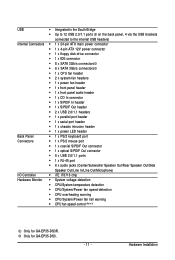
Hardware Installation Only for GA-EP35-DS3R. USB Š Integrated in the South Bridge Š Up to 12 USB 2.0/1.1 ports (8 on the back panel, 4 via the USB brackets connected to the internal ...; CPU/System/Power fan speed detection Š CPU overheating warning Š CPU/System/Power fan fail warning Š CPU fan speed control (Note 3) Only for GA-EP35-DS3. - 11 -
Hardware Installation Only for GA-EP35-DS3R. USB Š Integrated in the South Bridge Š Up to 12 USB 2.0/1.1 ports (8 on the back panel, 4 via the USB brackets connected to the internal ...; CPU/System/Power fan speed detection Š CPU overheating warning Š CPU/System/Power fan fail warning Š CPU fan speed control (Note 3) Only for GA-EP35-DS3. - 11 -
Manual
Page 12
... Windows Vista (on ICH9, hot plug is supported will depend on the CPU cooler you install. (Note 4) Available functions in Easytune may differ by the GIGABYTE SATA2 controller. (Refer to chipset limitation, Intel ICH9R RAID driver does not support Windows 2000 operating system. GA-EP35-DS3R/DS3 Motherboard - 12 -
... Windows Vista (on ICH9, hot plug is supported will depend on the CPU cooler you install. (Note 4) Available functions in Easytune may differ by the GIGABYTE SATA2 controller. (Refer to chipset limitation, Intel ICH9R RAID driver does not support Windows 2000 operating system. GA-EP35-DS3R/DS3 Motherboard - 12 -

Manual
Page 14
... fingers. Step 4: Hold the CPU with the socket alignment keys) and gently insert the CPU into its locked position. Step 2: Remove the protective socket cover. GA-EP35-DS3R/DS3 Motherboard - 14 - B. CPU Socket Lever Step 1: Completely raise the CPU socket lever. Step 3: Lift the metal load plate on the CPU socket. Step 5: Once the...
... fingers. Step 4: Hold the CPU with the socket alignment keys) and gently insert the CPU into its locked position. Step 2: Remove the protective socket cover. GA-EP35-DS3R/DS3 Motherboard - 14 - B. CPU Socket Lever Step 1: Completely raise the CPU socket lever. Step 3: Lift the metal load plate on the CPU socket. Step 5: Once the...
Manual
Page 16
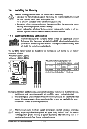
...DS=Double-Sided, "- -"=No Memory) DDRII1 DDRII2 DDRII3 DDRII4 Due to prevent hardware damage. • Memory modules have a foolproof design. GA-EP35-DS3R/DS3 Motherboard - 16 - After the memory is operating in Dual Channel mode. 1. Four Modules DS/SS DS/SS DS/SS DDRII4 - ... This motherboard provides four DDR2 memory sockets and supports Dual Channel Technology. Dual Channel mode cannot be used . (Go to GIGABYTE's website for optimum performance. 1-4 Installing the Memory Read the following guidelines before installing the memory in Flex Memory Mode will ...
...DS=Double-Sided, "- -"=No Memory) DDRII1 DDRII2 DDRII3 DDRII4 Due to prevent hardware damage. • Memory modules have a foolproof design. GA-EP35-DS3R/DS3 Motherboard - 16 - After the memory is operating in Dual Channel mode. 1. Four Modules DS/SS DS/SS DS/SS DDRII4 - ... This motherboard provides four DDR2 memory sockets and supports Dual Channel Technology. Dual Channel mode cannot be used . (Go to GIGABYTE's website for optimum performance. 1-4 Installing the Memory Read the following guidelines before installing the memory in Flex Memory Mode will ...
Manual
Page 18
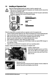
... unplug the power cord from the power outlet before you begin to install an expansion card: • Make sure the motherboard supports the expansion card. GA-EP35-DS3R/DS3 Motherboard - 18 - Align the card with your expansion card in the expansion slot. 1. Turn on the card are completely inserted into the PCI Express x16...
... unplug the power cord from the power outlet before you begin to install an expansion card: • Make sure the motherboard supports the expansion card. GA-EP35-DS3R/DS3 Motherboard - 18 - Align the card with your expansion card in the expansion slot. 1. Turn on the card are completely inserted into the PCI Express x16...
Manual
Page 20
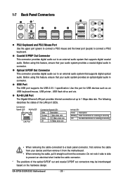
...; When removing the cable, pull it side to side to prevent an electrical short inside the cable connector. * The positions of the LAN port LEDs. GA-EP35-DS3R/DS3 Motherboard - 20 - Coaxial S/PDIF Out Connector This connector provides digital audio out to 1 Gbps data rate. Before using this port for USB devices such as...
...; When removing the cable, pull it side to side to prevent an electrical short inside the cable connector. * The positions of the LAN port LEDs. GA-EP35-DS3R/DS3 Motherboard - 20 - Coaxial S/PDIF Out Connector This connector provides digital audio out to 1 Gbps data rate. Before using this port for USB devices such as...
Manual
Page 22
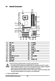
Only for GA-EP35-DS3R. GA-EP35-DS3R/DS3 Motherboard - 22 - 1-8 Internal Connectors 1 3 23 2 7 14 4 5 6 12 21 17 9 16 10 8 15 19 20 18 22 11 13 1) ATX_12V 2) ATX 3) CPU_FAN 4) SYS_FAN1 5) SYS_FAN2 6) PWR_FAN 7) FDD 8) ...
Only for GA-EP35-DS3R. GA-EP35-DS3R/DS3 Motherboard - 22 - 1-8 Internal Connectors 1 3 23 2 7 14 4 5 6 12 21 17 9 16 10 8 15 19 20 18 22 11 13 1) ATX_12V 2) ATX 3) CPU_FAN 4) SYS_FAN1 5) SYS_FAN2 6) PWR_FAN 7) FDD 8) ...
Manual
Page 24
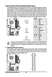
... a stripe of a CPU fan with colorcoded power connector wires. The motherboard supports CPU fan speed control, which requires the use of different color. 34 33 GA-EP35-DS3R/DS3 Motherboard 2 1 - 24 - Definition 1 CPU_FAN 1 GND 2 +12V 3 Sense 4 Speed Control 1 SYS_FAN2 SYS_FAN2: Pin No. 1 2 3 4 Definition GND Speed Control Sense +5V 1 SYS_FAN1 / PWR_FAN SYS_FAN1 / PWR_FAN : Pin No...
... a stripe of a CPU fan with colorcoded power connector wires. The motherboard supports CPU fan speed control, which requires the use of different color. 34 33 GA-EP35-DS3R/DS3 Motherboard 2 1 - 24 - Definition 1 CPU_FAN 1 GND 2 +12V 3 Sense 4 Speed Control 1 SYS_FAN2 SYS_FAN2: Pin No. 1 2 3 4 Definition GND Speed Control Sense +5V 1 SYS_FAN1 / PWR_FAN SYS_FAN1 / PWR_FAN : Pin No...
Manual
Page 25
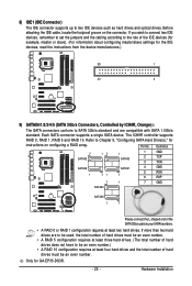
... 1 71 SATAII1 7 4 GND 5 RXN 6 RXP 7 1 7 GND SATAII4 SATAII5 1 7 Please connect the L-shaped end of the SATA 3Gb/s cable to Chapter 5, "Configuring SATA Hard Drive(s)," for GA-EP35-DS3R. - 25 - Refer to your SATA hard drive. • A RAID 0 or RAID 1 configuration requires at least three hard drives. (The total number of hard drives does...
... 1 71 SATAII1 7 4 GND 5 RXN 6 RXP 7 1 7 GND SATAII4 SATAII5 1 7 Please connect the L-shaped end of the SATA 3Gb/s cable to Chapter 5, "Configuring SATA Hard Drive(s)," for GA-EP35-DS3R. - 25 - Refer to your SATA hard drive. • A RAID 0 or RAID 1 configuration requires at least three hard drives. (The total number of hard drives does...
Manual
Page 26
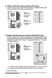
... and are to your SATA hard drive. If more than two hard drives are compatible with SATA 1.5Gb/s standard. GA-EP35-DS3R/DS3 Motherboard - 26 - A RAID 0 or RAID 1 configuration requires at least two hard drives. The GIGABYTE SATA2 controller supports RAID 0 and RAID 1. Definition 1 GND 7 1 2 TXP GSATAII0 3 TXN GSATAII1 4 GND 5 RXN 1 7 6 RXP 7 GND Please connect...
... and are to your SATA hard drive. If more than two hard drives are compatible with SATA 1.5Gb/s standard. GA-EP35-DS3R/DS3 Motherboard - 26 - A RAID 0 or RAID 1 configuration requires at least two hard drives. The GIGABYTE SATA2 controller supports RAID 0 and RAID 1. Definition 1 GND 7 1 2 TXP GSATAII0 3 TXN GSATAII1 4 GND 5 RXN 1 7 6 RXP 7 GND Please connect...

Manual
Page 28
.... • RES (Reset Switch, Green): Connects to perform a normal restart. • NC (Purple): No connection The front panel design may differ by issuing a beep code. GA-EP35-DS3R/DS3 Motherboard - 28 - Note the positive and negative pins before connecting the cables. Message/Power/ Power Sleep LED Switch Speaker MSG+ MSG- You may issue beeps...
.... • RES (Reset Switch, Green): Connects to perform a normal restart. • NC (Purple): No connection The front panel design may differ by issuing a beep code. GA-EP35-DS3R/DS3 Motherboard - 28 - Note the positive and negative pins before connecting the cables. Message/Power/ Power Sleep LED Switch Speaker MSG+ MSG- You may issue beeps...
Manual
Page 30
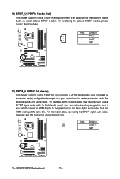
... In Header, Red) This header supports digital S/PDIF in and can connect to certain expansion cards like graphics cards and sound cards. Definition 1 SPDIFO 2 GND GA-EP35-DS3R/DS3 Motherboard - 30 - Definition 1 Power 2 SPDIFI 3 GND 17) SPDIF_O (S/PDIF Out Header) This header supports digital S/PDIF out and connects a S/PDIF digital audio cable (provided by...
... In Header, Red) This header supports digital S/PDIF in and can connect to certain expansion cards like graphics cards and sound cards. Definition 1 SPDIFO 2 GND GA-EP35-DS3R/DS3 Motherboard - 30 - Definition 1 Power 2 SPDIFI 3 GND 17) SPDIF_O (S/PDIF Out Header) This header supports digital S/PDIF out and connects a S/PDIF digital audio cable (provided by...