Manual
Page 7
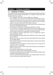
These stickers are required for the motherboard. •• Prior to wear an electrostatic discharge...placed on the motherboard or within an electrostatic shielding container. •• Before unplugging the power supply cable from the power outlet before installing or removing the motherboard or other hardware components. •• When ...connecting hardware components to the internal connectors on the computer power during the installation process can become damaged as a motherboard, CPU or memory. If you are uncertain ...
These stickers are required for the motherboard. •• Prior to wear an electrostatic discharge...placed on the motherboard or within an electrostatic shielding container. •• Before unplugging the power supply cable from the power outlet before installing or removing the motherboard or other hardware components. •• When ...connecting hardware components to the internal connectors on the computer power during the installation process can become damaged as a motherboard, CPU or memory. If you are uncertain ...
Manual
Page 14
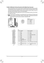
... be used (300W or greater). The 12V power connector mainly supplies power to the power connector in the correct orientation. Connect the power supply cable to the CPU. If the 12V power connector is recommended that a power supply that does not provide the required power, the result can supply enough stable power to all devices are properly installed. 1/2) ATX_12V...
... be used (300W or greater). The 12V power connector mainly supplies power to the power connector in the correct orientation. Connect the power supply cable to the CPU. If the 12V power connector is recommended that a power supply that does not provide the required power, the result can supply enough stable power to all devices are properly installed. 1/2) ATX_12V...
Manual
Page 18
... a S/PDIF digital audio cable (provided by default. •• Audio signals will make the device unable to this header. You may require you to use a S/PDIF digital audio cable for digital audio output from your motherboard to your graphics card if you wish to connect an... read the manual for digital audio output from the HDMI display at the same time. Definition Pin No. Definition 1 2 1 MIC2_L 2 GND 1 MIC 2 GND 3 MIC2_R 3 MIC Power 9 10 4 -ACZ_DET 4 NC 5 LINE2_R 5 Line Out (R) 6 GND 6 NC 7 FAUDIO_JD 7 NC 8 No Pin 8 No Pin 9 LINE2_L 9 Line Out (L) 10 GND 10 ...
... a S/PDIF digital audio cable (provided by default. •• Audio signals will make the device unable to this header. You may require you to use a S/PDIF digital audio cable for digital audio output from your motherboard to your graphics card if you wish to connect an... read the manual for digital audio output from the HDMI display at the same time. Definition Pin No. Definition 1 2 1 MIC2_L 2 GND 1 MIC 2 GND 3 MIC2_R 3 MIC Power 9 10 4 -ACZ_DET 4 NC 5 LINE2_R 5 Line Out (R) 6 GND 6 NC 7 FAUDIO_JD 7 NC 8 No Pin 8 No Pin 9 LINE2_L 9 Line Out (L) 10 GND 10 ...

Manual
Page 19
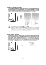
Pin No. Definition 2 10 1 9 1 Power (5V) 2 Power (5V) 3 USB DX- 4 USB DY- 5 USB DX+ 6 USB DY+ 7 GND 8 GND 9 No Pin 10 NC •• Do not plug the IEEE 1394 bracket (2x5-... the USB bracket, be sure to turn off your computer and unplug the power cord from the power outlet to prevent damage to USB 2.0/1.1 specification. Each USB header can provide two USB ports via an optional USB bracket. This function requires a chassis with chassis intrusion detection design. 11) F_USB1/F_USB2 (USB 2.0/1.1 Headers) The...
Pin No. Definition 2 10 1 9 1 Power (5V) 2 Power (5V) 3 USB DX- 4 USB DY- 5 USB DX+ 6 USB DY+ 7 GND 8 GND 9 No Pin 10 NC •• Do not plug the IEEE 1394 bracket (2x5-... the USB bracket, be sure to turn off your computer and unplug the power cord from the power outlet to prevent damage to USB 2.0/1.1 specification. Each USB header can provide two USB ports via an optional USB bracket. This function requires a chassis with chassis intrusion detection design. 11) F_USB1/F_USB2 (USB 2.0/1.1 Headers) The...

Manual
Page 28
...USB-FDD, USB-ZIP, USB-CDROM, USB-HDD, Legacy LAN, Disabled. && Password Check Specifies whether a password is required for booting the system and for entering the BIOS Setup program. && HDD S.M.A.R.T. This feature allows your hard drive. ...Away Mode allows the system to display the GIGABYTE Logo at system startup. Use the up or down arrow key to select a device and press to...) && Away Mode Enables or disables Away Mode in a low-power mode that appears off. (Default: Disabled) && Full Screen LOGO Show Allows you enter BIOS Setup.
...USB-FDD, USB-ZIP, USB-CDROM, USB-HDD, Legacy LAN, Disabled. && Password Check Specifies whether a password is required for booting the system and for entering the BIOS Setup program. && HDD S.M.A.R.T. This feature allows your hard drive. ...Away Mode allows the system to display the GIGABYTE Logo at system startup. Use the up or down arrow key to select a device and press to...) && Away Mode Enables or disables Away Mode in a low-power mode that appears off. (Default: Disabled) && Full Screen LOGO Show Allows you enter BIOS Setup.

