
Manual
Page 1
GA-8I915G-MFD Intel® Pentium® 4 LGA775 Processor Motherboard User's Manual Rev. 2103 12ME-8I915GMFD-2103 This product must not be disposed of with your other household waste and must be handed over to a designated collection point for the recycling of waste electrical and electronic equipment !
GA-8I915G-MFD Intel® Pentium® 4 LGA775 Processor Motherboard User's Manual Rev. 2103 12ME-8I915GMFD-2103 This product must not be disposed of with your other household waste and must be handed over to a designated collection point for the recycling of waste electrical and electronic equipment !

Manual
Page 2
Motherboard GA-8I915G-MFD Jun. 11, 2004 Motherboard GA-8I915G-MFD Jun. 11, 2004
Motherboard GA-8I915G-MFD Jun. 11, 2004 Motherboard GA-8I915G-MFD Jun. 11, 2004

Manual
Page 4
Table of Contents GA-8I915G-MFD Motherboard Layout 6 Block Diagram ...7 Chapter 1 Hardware Installation 9 1-1 Considerations Prior to Installation 9 1-2 Feature Summary 10 1-3 Installation of the CPU and Heatsink 12 1-3-1 Installation of the CPU ...
Table of Contents GA-8I915G-MFD Motherboard Layout 6 Block Diagram ...7 Chapter 1 Hardware Installation 9 1-1 Considerations Prior to Installation 9 1-2 Feature Summary 10 1-3 Installation of the CPU and Heatsink 12 1-3-1 Installation of the CPU ...

Manual
Page 6
GA-8I915G-MFD Motherboard Layout KB_MS SPDIF_O SPDIF_I SYS_FAN CPU_FAN IT8712 IR ATX LPT LAN VGA R_USB ATX_12V LGA775 GA-8I915G-MFD DDRII1 DDRII2 DDRII3 DDRII4 IDE USB AUDIO1 AUDIO2 RTL8110S CODEC AZALIA_FP Intel 915G PCIE_1 COMA COMB PCIE_16 PCI1 FDD S_ATA3 BAT PCI2 ICH6 TSB43AB23 CLR_CMOS S_ATA0 S_ATA2 F2_1394 F1_1394 F_USB1 F_USB2 BIOS F_PANEL CD_IN S_ATA1 PWR_LED - 6 -
GA-8I915G-MFD Motherboard Layout KB_MS SPDIF_O SPDIF_I SYS_FAN CPU_FAN IT8712 IR ATX LPT LAN VGA R_USB ATX_12V LGA775 GA-8I915G-MFD DDRII1 DDRII2 DDRII3 DDRII4 IDE USB AUDIO1 AUDIO2 RTL8110S CODEC AZALIA_FP Intel 915G PCIE_1 COMA COMB PCIE_16 PCI1 FDD S_ATA3 BAT PCI2 ICH6 TSB43AB23 CLR_CMOS S_ATA0 S_ATA2 F2_1394 F1_1394 F_USB1 F_USB2 BIOS F_PANEL CD_IN S_ATA1 PWR_LED - 6 -

Manual
Page 10
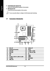
Center/Subwoofer Speaker Out ; For example, 4 GB of memory size will instead be shown as 3.xxGB memory during system startup. GA-8I915G-MFD Motherboard - 10 - MIC ; Side Speaker Out connection Š Supports SPDIF In/Out connection Š CD In Š IT8712 (Note 1) Due to 4GB memory) (Note 1) Š ...
Center/Subwoofer Speaker Out ; For example, 4 GB of memory size will instead be shown as 3.xxGB memory during system startup. GA-8I915G-MFD Motherboard - 10 - MIC ; Side Speaker Out connection Š Supports SPDIF In/Out connection Š CD In Š IT8712 (Note 1) Due to 4GB memory) (Note 1) Š ...

Manual
Page 12
... for HT Technology 1-3-1 Installation of the CPU Metal Lever Fig. 1 Gently lift the metal lever located on the CPU prior to the CPU during installation.) GA-8I915G-MFD Motherboard - 12 - It is installed on the CPU socket to your hardware specifications including the CPU, graphics card, memory, hard drive, etc. English 1-3 Installation of...
... for HT Technology 1-3-1 Installation of the CPU Metal Lever Fig. 1 Gently lift the metal lever located on the CPU prior to the CPU during installation.) GA-8I915G-MFD Motherboard - 12 - It is installed on the CPU socket to your hardware specifications including the CPU, graphics card, memory, hard drive, etc. English 1-3 Installation of...

Manual
Page 14
... is supported by the motherboard. Notch DDR II Fig.1 The DIMM socket has a notch, so the DIMM memory module can be installed in one direction. GA-8I915G-MFD Motherboard - 14 - Please make sure that memory of Memory Before installing the memory modules, please comply with each slot. A memory module can only fit in...
... is supported by the motherboard. Notch DDR II Fig.1 The DIMM socket has a notch, so the DIMM memory module can be installed in one direction. GA-8I915G-MFD Motherboard - 14 - Please make sure that memory of Memory Before installing the memory modules, please comply with each slot. A memory module can only fit in...

Manual
Page 15
GA-8I915G-MFD includes 4 DIMM sockets, and each Channel has two DIMM sockets as following: Channel A : DDR II 1, DDR II 2 Channel B : DDR II 3, DDR II 4 If you install ... the same channel, the Dual Channel Technology will operate only when those modules have the same memory size and type. English Dual Channel DDR II GA-8I915G-MFD supports the Dual Channel Technology. Two DDR II memory modules are installed (the same memory size and type): The Dual Channel Technology will double. Hardware...
GA-8I915G-MFD includes 4 DIMM sockets, and each Channel has two DIMM sockets as following: Channel A : DDR II 1, DDR II 2 Channel B : DDR II 3, DDR II 4 If you install ... the same channel, the Dual Channel Technology will operate only when those modules have the same memory size and type. English Dual Channel DDR II GA-8I915G-MFD supports the Dual Channel Technology. Two DDR II memory modules are installed (the same memory size and type): The Dual Channel Technology will double. Hardware...

Manual
Page 16
... you try to secure the slot bracket of the expansion card. 6. Remove your computer's chassis cover. 7. Power on the card are indeed seated in motherboard. 4. GA-8I915G-MFD Motherboard - 16 - Read the related expansion card's instruction document before install the expansion card into expansion slot in the slot. 5. Installing a PCI Express x 16 expansion...
... you try to secure the slot bracket of the expansion card. 6. Remove your computer's chassis cover. 7. Power on the card are indeed seated in motherboard. 4. GA-8I915G-MFD Motherboard - 16 - Read the related expansion card's instruction document before install the expansion card into expansion slot in the slot. 5. Installing a PCI Express x 16 expansion...
Manual
Page 18
... / S_ATA1 / S_ATA2 / S_ATA3 8) F_PANEL 9) PWR_LED 10) AZALIA_FP 11) CD_IN 12) F_USB1 / F_USB2 13) F1_1394 / F2_1394 14) IR 15) COMA 16) COMB 17) CLR_CMOS 18) BAT GA-8I915G-MFD Motherboard - 18 - Side Speaker Out Connect the side surround speakers to this connector. English Center/Subwoofer Speaker Out Connect the Center/Subwoofer speakers to this...
... / S_ATA1 / S_ATA2 / S_ATA3 8) F_PANEL 9) PWR_LED 10) AZALIA_FP 11) CD_IN 12) F_USB1 / F_USB2 13) F1_1394 / F2_1394 14) IR 15) COMA 16) COMB 17) CLR_CMOS 18) BAT GA-8I915G-MFD Motherboard - 18 - Side Speaker Out Connect the side surround speakers to this connector. English Center/Subwoofer Speaker Out Connect the Center/Subwoofer speakers to this...

Manual
Page 20
... Speed Control (Only for CPU_FAN) power connector and possesses a foolproof connection design. Please connect the red power connector wire to the pin1 position. 34 33 2 1 GA-8I915G-MFD Motherboard - 20 - Most coolers are : 360KB, 720KB, 1.2MB, 1.44MB and 2.88MB. English 3/4) CPU_FAN / SYS_FAN (Cooler Fan Power Connector) The cooler fan power connector supplies a +12V...
... Speed Control (Only for CPU_FAN) power connector and possesses a foolproof connection design. Please connect the red power connector wire to the pin1 position. 34 33 2 1 GA-8I915G-MFD Motherboard - 20 - Most coolers are : 360KB, 720KB, 1.2MB, 1.44MB and 2.88MB. English 3/4) CPU_FAN / SYS_FAN (Cooler Fan Power Connector) The cooler fan power connector supplies a +12V...

Manual
Page 22
... 2- Pin 3: NC Pin 4: Data(-) Open: Normal Operation Close: Reset Hardware System Open: Normal Operation Close: Power On/Off Pin 1: LED anode(+) Pin 2: LED cathode(-) NC GA-8I915G-MFD Motherboard - 22 -
... 2- Pin 3: NC Pin 4: Data(-) Open: Normal Operation Close: Reset Hardware System Open: Normal Operation Close: Power On/Off Pin 1: LED anode(+) Pin 2: LED cathode(-) NC GA-8I915G-MFD Motherboard - 22 -

Manual
Page 24
... USB cable, please contact your local dealer. 2 10 1 9 Pin No. 1 2 3 4 5 6 7 8 9 10 Definition Power Power USB DXUSB DyUSB DX+ USB Dy+ GND GND No Pin NC GA-8I915G-MFD Motherboard - 24 - Pin No. 1 1 2 3 4 Definition CD-L GND GND CD-R 12) F_ USB1 / F_USB2 (Front USB Connector) Be careful with the polarity of the front USB...
... USB cable, please contact your local dealer. 2 10 1 9 Pin No. 1 2 3 4 5 6 7 8 9 10 Definition Power Power USB DXUSB DyUSB DX+ USB Dy+ GND GND No Pin NC GA-8I915G-MFD Motherboard - 24 - Pin No. 1 1 2 3 4 Definition CD-L GND GND CD-R 12) F_ USB1 / F_USB2 (Front USB Connector) Be careful with the polarity of the front USB...

Manual
Page 26
Default doesn't include the "Shunter" to its default values by this jumper. 1 Open: Normal 1 Short: Clear CMOS GA-8I915G-MFD Motherboard - 26 - To clear CMOS, temporarily short 1-2 pin. For optional COM cable, please contact your local dealer. 2 10 1 9 Pin No. 1 2 3 4 5 6 7 8 9 10 Definition NDCD A/BNSIN A/B NSOUT A/B ...
Default doesn't include the "Shunter" to its default values by this jumper. 1 Open: Normal 1 Short: Clear CMOS GA-8I915G-MFD Motherboard - 26 - To clear CMOS, temporarily short 1-2 pin. For optional COM cable, please contact your local dealer. 2 10 1 9 Pin No. 1 2 3 4 5 6 7 8 9 10 Definition NDCD A/BNSIN A/B NSOUT A/B ...

Manual
Page 30
... & Exit Setup Time, Date, Hard Disk Type... If you can't find the setting you enter Award BIOS CMOS Setup Utility, the Main Menu (as usual. GA-8I915G-MFD Motherboard - 30 - English The Main Menu (For example: BIOS Ver. : F5) Once you want, please press "Ctrl+F1" to search the advanced option hidden...
... & Exit Setup Time, Date, Hard Disk Type... If you can't find the setting you enter Award BIOS CMOS Setup Utility, the Main Menu (as usual. GA-8I915G-MFD Motherboard - 30 - English The Main Menu (For example: BIOS Ver. : F5) Once you want, please press "Ctrl+F1" to search the advanced option hidden...

Manual
Page 32
... for faster system start up. The four options are used and the system will skip the automatic detection step and allow for automatic device detection. GA-8I915G-MFD Motherboard - 32 - Jan. English 2-1 Standard CMOS Features Date (mm:dd:yy) Time (hh:mm:ss) CMOS Setup Utility-Copyright (C) 1984-2004 Award Software Standard CMOS...
... for faster system start up. The four options are used and the system will skip the automatic detection step and allow for automatic device detection. GA-8I915G-MFD Motherboard - 32 - Jan. English 2-1 Standard CMOS Features Date (mm:dd:yy) Time (hh:mm:ss) CMOS Setup Utility-Copyright (C) 1984-2004 Award Software Standard CMOS...

Manual
Page 34
.... USB-FDD Select your boot device priority by CDROM. Press to move it down the list. CDROM Select your boot device priority by Hard Disk. GA-8I915G-MFD Motherboard - 34 - Hard Disk Boot Priority Select boot sequence for onboard(or add-on cards) SCSI, RAID, etc. USB-HDD Select your boot device priority...
.... USB-FDD Select your boot device priority by CDROM. Press to move it down the list. CDROM Select your boot device priority by Hard Disk. GA-8I915G-MFD Motherboard - 34 - Hard Disk Boot Priority Select boot sequence for onboard(or add-on cards) SCSI, RAID, etc. USB-HDD Select your boot device priority...

Manual
Page 36
GA-8I915G-MFD Motherboard - 36 - English 2-3 Integrated Peripherals CMOS Setup Utility-Copyright (C) 1984-2004 Award Software Integrated Peripherals On-Chip Primary PCI IDE On-Chip SATA Mode x PATA ...
GA-8I915G-MFD Motherboard - 36 - English 2-3 Integrated Peripherals CMOS Setup Utility-Copyright (C) 1984-2004 Award Software Integrated Peripherals On-Chip Primary PCI IDE On-Chip SATA Mode x PATA ...

Manual
Page 38
... port and address is 378/IRQ7. (Default value) 278/IRQ5 3BC/IRQ7 Enable onboard LPT port and address is 3BC/IRQ7. Disable onboard Serial port 2. GA-8I915G-MFD Motherboard - 38 - Onboard H/W LAN Enabled Enable Onboard H/W LAN function. (Default value) Disabled Disable this function. (Default value) Onboard Serial Port 1 Auto 3F8/IRQ4 BIOS will...
... port and address is 378/IRQ7. (Default value) 278/IRQ5 3BC/IRQ7 Enable onboard LPT port and address is 3BC/IRQ7. Disable onboard Serial port 2. GA-8I915G-MFD Motherboard - 38 - Onboard H/W LAN Enabled Enable Onboard H/W LAN function. (Default value) Disabled Disable this function. (Default value) Onboard Serial Port 1 Auto 3F8/IRQ4 BIOS will...

Manual
Page 40
GA-8I915G-MFD Motherboard - 40 - Power On By Keyboard Password Disabled Enter from 1 to 5 characters) and press Enter to power on the system. AC BACK Function Soft-Off ...
GA-8I915G-MFD Motherboard - 40 - Power On By Keyboard Password Disabled Enter from 1 to 5 characters) and press Enter to power on the system. AC BACK Function Soft-Off ...