
Manual
Page 1
GA-7TESH2-RH Dual Xeon Processor Motherboard USER'S Manual Xeon® Processor Motherboard Rev. 1001 * The WEEE marking on the product indicates this product must not be disposed of with user's other household waste and must be handed over to a designated collection point for the recycling of waste electrical and electronic equipment!! * The WEEE marking applies only in European Union's member states.
GA-7TESH2-RH Dual Xeon Processor Motherboard USER'S Manual Xeon® Processor Motherboard Rev. 1001 * The WEEE marking on the product indicates this product must not be disposed of with user's other household waste and must be handed over to a designated collection point for the recycling of waste electrical and electronic equipment!! * The WEEE marking applies only in European Union's member states.

Manual
Page 2
... 58 Power ...60 Security ...62 Server ...62 2 English Table of Contents Table of Content Item Checklist 4 Chapter 1Introduction 5 1.1.Considerations Prior to Installation 5 1.2.Features Summary 6 1.3.GA-7TESH1-RH Motherboard Component 8 Chapter 2Hardware Installation Process 11 2.1.Installing Processor and CPU Haet Sink 11 2.1.1.Installing CPU ...11 2.1.2.Installing Heat Sink 12 2.2.Installing memory modules 13...
... 58 Power ...60 Security ...62 Server ...62 2 English Table of Contents Table of Content Item Checklist 4 Chapter 1Introduction 5 1.1.Considerations Prior to Installation 5 1.2.Features Summary 6 1.3.GA-7TESH1-RH Motherboard Component 8 Chapter 2Hardware Installation Process 11 2.1.Installing Processor and CPU Haet Sink 11 2.1.1.Installing CPU ...11 2.1.2.Installing Heat Sink 12 2.2.Installing memory modules 13...

Manual
Page 3
English GA-7TESH2-RH Motherboard System Management ...65 Console Redirection ...67 Boot ...69 Exit ...70 3
English GA-7TESH2-RH Motherboard System Management ...65 Console Redirection ...67 Boot ...69 Exit ...70 3

Manual
Page 4
Item Checklist The GA-7TESH2-RH motherboard Serial ATA cable x 6 I/O Shield Kit CD for motherboard driver & utility GA-7TESH2-RH quick reference guide Introduction * The items listed above are for reference only, and are subject to change without notice. 4
Item Checklist The GA-7TESH2-RH motherboard Serial ATA cable x 6 I/O Shield Kit CD for motherboard driver & utility GA-7TESH2-RH quick reference guide Introduction * The items listed above are for reference only, and are subject to change without notice. 4

Manual
Page 5
... or metal components placed on an uneven surface. 7. Please make sure there are connected. 4. Turning on top of electrostatic discharge (ESD). English GA-7TESH2-RH Motherboard Chapter 1 Introduction 1.1. To prevent damage to the motherboard, please do not allow screws to the user. 8. Damage due to natural disaster,... Damage as a result of the motherboard or any metal leads or connectors. 3. Installation Notices 1. Damage due to be an unofficial Gigabyte product. 5 It is switched off the computer and unplug its components. 5. Product determined to use of Non-Warranty 1.
... or metal components placed on an uneven surface. 7. Please make sure there are connected. 4. Turning on top of electrostatic discharge (ESD). English GA-7TESH2-RH Motherboard Chapter 1 Introduction 1.1. To prevent damage to the motherboard, please do not allow screws to the user. 8. Damage due to natural disaster,... Damage as a result of the motherboard or any metal leads or connectors. 3. Installation Notices 1. Damage due to be an unofficial Gigabyte product. 5 It is switched off the computer and unplug its components. 5. Product determined to use of Non-Warranty 1.

Manual
Page 6
1.2. Features Summary Introduction Form Factor CPU Chipset Memory I/O Control Expansion Slots SATA RAID Controller On-Board VGA On-Board LAN Internal Connector 12" x 13" EATX size form factor, 8 layers PCB Supports Dual Intel® Xeon® Nehalem-EP 2S processors Xeon® Quad Core in LGA 1366 socket Supports QuickPath Interconnect up to 6.4GT/s Enhanced Intel SpeedStep Technology (EIST) & Demand Based Switch (DBS) Support Intel Virtualization Technology (VT) Intel® 5520 (Tylersburg-36D) Chipset Intel® ...
1.2. Features Summary Introduction Form Factor CPU Chipset Memory I/O Control Expansion Slots SATA RAID Controller On-Board VGA On-Board LAN Internal Connector 12" x 13" EATX size form factor, 8 layers PCB Supports Dual Intel® Xeon® Nehalem-EP 2S processors Xeon® Quad Core in LGA 1366 socket Supports QuickPath Interconnect up to 6.4GT/s Enhanced Intel SpeedStep Technology (EIST) & Demand Based Switch (DBS) Support Intel Virtualization Technology (VT) Intel® 5520 (Tylersburg-36D) Chipset Intel® ...

Manual
Page 7
English GA-7TESH2-RH Motherboard Rear Panel I/O Hardware Monitor BIOS Additional Features &#...
English GA-7TESH2-RH Motherboard Rear Panel I/O Hardware Monitor BIOS Additional Features &#...

Manual
Page 8
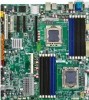
GA-7TESH2-RH Motherboard Component Code Description CPU1 Primary CPU CPU2 Secondary CPU U82 Intel Tylersburg-36D IOH U60 Intel ICH10R U188 Winbond W83792G U6 Intel 82576EB GbE ...
GA-7TESH2-RH Motherboard Component Code Description CPU1 Primary CPU CPU2 Secondary CPU U82 Intel Tylersburg-36D IOH U60 Intel ICH10R U188 Winbond W83792G U6 Intel 82576EB GbE ...
Manual
Page 9
... jumper 67. DIMMB2 43. GBE1_2 Gigabit LAN ports 57. PCI-E1 39. DIMMF2 50. USB USB ports 54. JP_STRP2 PilotII firmware upgrade jumper 69. English GA-7TESH2-RH Motherboard No Code Description 38. DIMMB1 42. DIMMF1 51. ATX 24-pin Power connector 59. 12V_AUX2 CPU2 8-pin Power connector 60. 12V_AUX1 CPU1 8-pin Power...
... jumper 67. DIMMB2 43. GBE1_2 Gigabit LAN ports 57. PCI-E1 39. DIMMF2 50. USB USB ports 54. JP_STRP2 PilotII firmware upgrade jumper 69. English GA-7TESH2-RH Motherboard No Code Description 38. DIMMB1 42. DIMMF1 51. ATX 24-pin Power connector 59. 12V_AUX2 CPU2 8-pin Power connector 60. 12V_AUX1 CPU1 8-pin Power...

Manual
Page 10
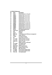
English GA-7TESH2-RH Motherboard 19 70 11 68 10 9 8 13 67 69 17 12 34 35 36 37 57 18 25 24 23 64 662566 63 4 22 61 21 20 16 14 56 55 6 27 5 2 38 3940 41424344 7 54 53 52 51 32 33 59 58 45 46 47484950 3 15 31 30 1 26 29 28 60 10
English GA-7TESH2-RH Motherboard 19 70 11 68 10 9 8 13 67 69 17 12 34 35 36 37 57 18 25 24 23 64 662566 63 4 22 61 21 20 16 14 56 55 6 27 5 2 38 3940 41424344 7 54 53 52 51 32 33 59 58 45 46 47484950 3 15 31 30 1 26 29 28 60 10

Manual
Page 11
Never force the processor into locked position. 11 Installing CPU Step 1 Raise the metal locking lever on the CPU socket. Step 2 Remove the plastic covering on the socket. If you do not match the CPU socket Pin 1 and CPU cut edge well, it will overheat without the heatsink and/or fan, resulting in one orientation. The CPU only fits in permanent irreparable damage. 2. Step 4 Once the CPU is supported by the motherboard. 5. Hardware Installation Process Chapter 2 Hardware Installation Process 2.1. Apply thermal grease on the processor before placing cooling fan. 4. The ...
Never force the processor into locked position. 11 Installing CPU Step 1 Raise the metal locking lever on the CPU socket. Step 2 Remove the plastic covering on the socket. If you do not match the CPU socket Pin 1 and CPU cut edge well, it will overheat without the heatsink and/or fan, resulting in one orientation. The CPU only fits in permanent irreparable damage. 2. Step 4 Once the CPU is supported by the motherboard. 5. Hardware Installation Process Chapter 2 Hardware Installation Process 2.1. Apply thermal grease on the processor before placing cooling fan. 4. The ...

Manual
Page 12
Step 3 Connect processor fan can cable to the processor socket. English GA-7TESH2-RH Motherboard 2.1.2. Step 2 Secure the cooing fan with screws. Installing Heat Sink Step 1 Attach the heat sink clip to the processor fanconnector 2 2 2 1 12
Step 3 Connect processor fan can cable to the processor socket. English GA-7TESH2-RH Motherboard 2.1.2. Step 2 Secure the cooing fan with screws. Installing Heat Sink Step 1 Attach the heat sink clip to the processor fanconnector 2 2 2 1 12

Manual
Page 13
Before installing or removing memory modules, please make sure that the memory is switched off to prevent hardware damage. 3. Memory sockets for Processor 2 Memory sockets for Processor 1 13 If you are designed so that the computer power is supported by the motherboard. Memory modules are unable to use the memory with similar capacity, specifications and brand. 2. The motherboard supports DDR3 memory modules, whereby BIOS will automatically detect memory capacity and specifications. The memory capacity used can be inserted only in only one direction. Hardware ...
Before installing or removing memory modules, please make sure that the memory is switched off to prevent hardware damage. 3. Memory sockets for Processor 2 Memory sockets for Processor 1 13 If you are designed so that the computer power is supported by the motherboard. Memory modules are unable to use the memory with similar capacity, specifications and brand. 2. The motherboard supports DDR3 memory modules, whereby BIOS will automatically detect memory capacity and specifications. The memory capacity used can be inserted only in only one direction. Hardware ...

Manual
Page 14
Close the plastic clip at both edges of the DIMM slots to remove the DIMM module. 1 2 2 DIMMF1 DIMME1 DIMMF2 DIMME2 DIMMD1 DIMMD2 CPU2 CPU1 DIMMA2 DIMMA1 DIMMB2 DIMMB1 DIMMC2 DIMMC1 14 NOTE! Step 2. Step 3. DIMM must be populated in matched pairs. Reverse the installation steps when you wish to lock the DIMM module. For dual-channel operation, DIMMs must be installed in order starting from DIMMA1/D1 socket. Insert the DIMM memory module vertically into the DIMM slot, and push it down. Hardware Installation Process Installation Steps: Step 1.
Close the plastic clip at both edges of the DIMM slots to remove the DIMM module. 1 2 2 DIMMF1 DIMME1 DIMMF2 DIMME2 DIMMD1 DIMMD2 CPU2 CPU1 DIMMA2 DIMMA1 DIMMB2 DIMMB1 DIMMC2 DIMMC1 14 NOTE! Step 2. Step 3. DIMM must be populated in matched pairs. Reverse the installation steps when you wish to lock the DIMM module. For dual-channel operation, DIMMs must be installed in order starting from DIMMA1/D1 socket. Insert the DIMM memory module vertically into the DIMM slot, and push it down. Hardware Installation Process Installation Steps: Step 1.

Manual
Page 15
English GA-7TESH2-RH Motherboard U-DIMM Population Table Interleave Channel A Channel B Channel C mode DIMMA1/D1 DIMMA2/D2 DIMMB1/E1 DIMMB2/E2 DIMMC1/F1 DIMMC2/F2 Total Memory Single Channel Dual Channel 1GB 2GB 4GB 1GB 2GB 4GB 1GB 2GB 4GB 1GB 2GB 4GB 1GB 2GB 4GB 1GB 2GB 4GB 1GB 2GB 4GB 1GB 2GB 4GB 2GB 4GB 8GB 4GB 8GB 16GB Three Channel 1GB 2GB 4GB 1GB 1GB 1GB 2GB 4GB 1GB 1GB 1GB 2GB 4GB 1GB 1GB 3GB 6GB 16GB 6GB 2GB 4GB 2GB 4GB 2GB 4GB 2GB 4GB 2GB 4GB 2GB 4GB 12GB 24GB 15
English GA-7TESH2-RH Motherboard U-DIMM Population Table Interleave Channel A Channel B Channel C mode DIMMA1/D1 DIMMA2/D2 DIMMB1/E1 DIMMB2/E2 DIMMC1/F1 DIMMC2/F2 Total Memory Single Channel Dual Channel 1GB 2GB 4GB 1GB 2GB 4GB 1GB 2GB 4GB 1GB 2GB 4GB 1GB 2GB 4GB 1GB 2GB 4GB 1GB 2GB 4GB 1GB 2GB 4GB 2GB 4GB 8GB 4GB 8GB 16GB Three Channel 1GB 2GB 4GB 1GB 1GB 1GB 2GB 4GB 1GB 1GB 1GB 2GB 4GB 1GB 1GB 3GB 6GB 16GB 6GB 2GB 4GB 2GB 4GB 2GB 4GB 2GB 4GB 2GB 4GB 2GB 4GB 12GB 24GB 15

Manual
Page 16
English GA-7TESH2-RH Motherboard R-DIMM Population Table Interleave Channel A Channel B Channel C mode DIMMA1/D1 DIMMA2/D2 DIMMB1/E1 DIMMB2/E2 DIMMC1/F1 DIMMC2/F2 Total Memory Single Channel 1GB 2GB 4GB 8GB 1GB 2GB 4GB 1GB 2GB 4GB 1GB 2GB 4GB 8GB 2GB 4GB 8GB Dual Channel Three Channel 8GB 1GB 2GB 4GB 8GB 1GB 2GB 4GB 8GB 1GB 2GB 4GB 8GB 1GB 2GB 4GB 8GB 1GB 2GB 4GB 8GB 8GB 1GB 2GB 4GB 8GB 1GB 2GB 4GB 8GB 1GB 2GB 4GB 8GB 1GB 2GB 4GB 8GB 1GB 2GB 4GB 8GB 1GB 2GB 4GB 8GB 1GB 2GB 4GB 8GB 1GB 2GB 4GB 8GB 16GB 4GB 8GB 16GB 32GB 3GB 6GB 12GB 24GB 6GB 12GB 24GB 48GB 16
English GA-7TESH2-RH Motherboard R-DIMM Population Table Interleave Channel A Channel B Channel C mode DIMMA1/D1 DIMMA2/D2 DIMMB1/E1 DIMMB2/E2 DIMMC1/F1 DIMMC2/F2 Total Memory Single Channel 1GB 2GB 4GB 8GB 1GB 2GB 4GB 1GB 2GB 4GB 1GB 2GB 4GB 8GB 2GB 4GB 8GB Dual Channel Three Channel 8GB 1GB 2GB 4GB 8GB 1GB 2GB 4GB 8GB 1GB 2GB 4GB 8GB 1GB 2GB 4GB 8GB 1GB 2GB 4GB 8GB 8GB 1GB 2GB 4GB 8GB 1GB 2GB 4GB 8GB 1GB 2GB 4GB 8GB 1GB 2GB 4GB 8GB 1GB 2GB 4GB 8GB 1GB 2GB 4GB 8GB 1GB 2GB 4GB 8GB 1GB 2GB 4GB 8GB 16GB 4GB 8GB 16GB 32GB 3GB 6GB 12GB 24GB 6GB 12GB 24GB 48GB 16

Manual
Page 17
I/O Back Panel Introduction 17 Connect ribbon cables, cabinet wires, and power supply 2.3.1. Hardware Installation Process 2.3.
I/O Back Panel Introduction 17 Connect ribbon cables, cabinet wires, and power supply 2.3.1. Hardware Installation Process 2.3.

Manual
Page 18
... OS supports USB controller. KVM Server Management 10/100 LAN Port The LAN port provides Internet connection with data transfer speeds of 10/100Mbps. English GA-7TESH2-RH Motherboard PS/2 Keyboard and PS/2 Mouse Connector To install a PS/2 port keyboard and mouse, plug the mouse to the upper port (green) and the keyboard...
... OS supports USB controller. KVM Server Management 10/100 LAN Port The LAN port provides Internet connection with data transfer speeds of 10/100Mbps. English GA-7TESH2-RH Motherboard PS/2 Keyboard and PS/2 Mouse Connector To install a PS/2 port keyboard and mouse, plug the mouse to the upper port (green) and the keyboard...

Manual
Page 19
LAN LED Description LED2 (Green/Yellow) Hardware Installation Process LED1 (Green) Name LED1 LED2 Color Green Green Green Green Green Yellow Yellow Condition ON BLINK OFF OFF BLINK ON BLINK ON BLINK Description LAN Link / no Access LAN Access Idle 10Mbps connection Port identification with 10 Mbps connection 100Mbps connection Port identification with 100Mbps connection 1Gbps connection Port identification with 1Gbps connection 19
LAN LED Description LED2 (Green/Yellow) Hardware Installation Process LED1 (Green) Name LED1 LED2 Color Green Green Green Green Green Yellow Yellow Condition ON BLINK OFF OFF BLINK ON BLINK ON BLINK Description LAN Link / no Access LAN Access Idle 10Mbps connection Port identification with 10 Mbps connection 100Mbps connection Port identification with 100Mbps connection 1Gbps connection Port identification with 1Gbps connection 19

Manual
Page 20
.... SATA3 (SATA data cable connector) 12. CPU_FAN2 (CPU1 fan cable connector) 18. SYS_FAN3 (System fan connector) 21. SYS_FAN5 (System fan connector) 23. IPMB2 26. English GA-7TESH2-RH Motherboard 2.4. SATA2 (SATA data cable connector) 11. SATA1 (SATA data cable connector) 10. SATA5 (SATA data cable connector 14. J3 SMBus 20 ATX 2. 12V_AUX1 3. 12V_AUX2...
.... SATA3 (SATA data cable connector) 12. CPU_FAN2 (CPU1 fan cable connector) 18. SYS_FAN3 (System fan connector) 21. SYS_FAN5 (System fan connector) 23. IPMB2 26. English GA-7TESH2-RH Motherboard 2.4. SATA2 (SATA data cable connector) 11. SATA1 (SATA data cable connector) 10. SATA5 (SATA data cable connector 14. J3 SMBus 20 ATX 2. 12V_AUX1 3. 12V_AUX2...