Use and Care Manual
Page 2
... 13 Care and Cleaning Draining 14 Extended Shut-Down 14 Maintenance 14 Troubleshooting Tips Before You Call For Service 15 Customer Service Parts List 16 Wiring Diagram 18 Product Registration 19 2 IMPORTANT! This symbol alerts you a great deal of time and money over the life of Troubleshooting Tips first, you may result...
... 13 Care and Cleaning Draining 14 Extended Shut-Down 14 Maintenance 14 Troubleshooting Tips Before You Call For Service 15 Customer Service Parts List 16 Wiring Diagram 18 Product Registration 19 2 IMPORTANT! This symbol alerts you a great deal of time and money over the life of Troubleshooting Tips first, you may result...
Use and Care Manual
Page 8
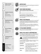
... 25 25 30 40 45 50 50 - 480V 15 15 15 15 15 20 25 25 30 30 35 Copper Wire Size AWG Based on National Electric Code. The branch circuit wiring should be electrically isolated. Table 310-16 (75°C) 208V 12 10 10 10 8 8 8 - - - - 240V ... in this manual for use as a grounding conductor and installed with copper conductors, overcurrent protective device and suitable disconnecting means must conform to wiring diagrams in the piping and water heater does not provide sufficient conduction for the purpose. Non-metallic piping, dielectric unions, flexible connectors etc. It...
... 25 25 30 40 45 50 50 - 480V 15 15 15 15 15 20 25 25 30 30 35 Copper Wire Size AWG Based on National Electric Code. The branch circuit wiring should be electrically isolated. Table 310-16 (75°C) 208V 12 10 10 10 8 8 8 - - - - 240V ... in this manual for use as a grounding conductor and installed with copper conductors, overcurrent protective device and suitable disconnecting means must conform to wiring diagrams in the piping and water heater does not provide sufficient conduction for the purpose. Non-metallic piping, dielectric unions, flexible connectors etc. It...
Use and Care Manual
Page 18
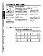
... THERMOSTAT Care and Cleaning Troubleshooting Tips Customer Service 18 BLACK RED JUNCTION BOX 1 3 2 4 1 4 2 YELLOW BLUE UPPER THERMOSTAT & HIGH TEMP. Operating Instructions Installation Instructions Safety Instructions Wiring diagrams. Wiring Diagrams for Type-59T Therm-o-disc Thermostats Single Element Models L1 G* L2 BRANCH CIRCUIT TO ELECTRICAL DISTRIBUTION PANEL 240 V. BLACK RED JUNCTION BOX 1 3 THERMOSTAT & HIGH TEMP...
... THERMOSTAT Care and Cleaning Troubleshooting Tips Customer Service 18 BLACK RED JUNCTION BOX 1 3 2 4 1 4 2 YELLOW BLUE UPPER THERMOSTAT & HIGH TEMP. Operating Instructions Installation Instructions Safety Instructions Wiring diagrams. Wiring Diagrams for Type-59T Therm-o-disc Thermostats Single Element Models L1 G* L2 BRANCH CIRCUIT TO ELECTRICAL DISTRIBUTION PANEL 240 V. BLACK RED JUNCTION BOX 1 3 THERMOSTAT & HIGH TEMP...


