
Use and Care Manual
Page 1
Gas Downdraft Cooktop ge.com Safety Instructions . . .2-7 Operating Instructions Downdraft Vent System . . .10 Features 8 Gas Surface Burners 9 Using Your Cooktop . . . . . .10 Care and Cleaning Burner Assemblies 11 Burner Caps, Heads and Electrodes 11 Burner Grates, Vent Grille ...28, 29 Exhaust Blower Ratings . . .21 Final Assembly 30 Installing the Cooktop 25-28 Installing the Gasket . . . . . .24 Power Supply 23 Preparation 17-19 Safety Precautions 15 Unpacking the Cooktop 16, 24 Owner's Manual & Installation Instructions PGP989 Write the model and serial numbers here: Model ...
Gas Downdraft Cooktop ge.com Safety Instructions . . .2-7 Operating Instructions Downdraft Vent System . . .10 Features 8 Gas Surface Burners 9 Using Your Cooktop . . . . . .10 Care and Cleaning Burner Assemblies 11 Burner Caps, Heads and Electrodes 11 Burner Grates, Vent Grille ...28, 29 Exhaust Blower Ratings . . .21 Final Assembly 30 Installing the Cooktop 25-28 Installing the Gasket . . . . . .24 Power Supply 23 Preparation 17-19 Safety Precautions 15 Unpacking the Cooktop 16, 24 Owner's Manual & Installation Instructions PGP989 Write the model and serial numbers here: Model ...
Use and Care Manual
Page 2
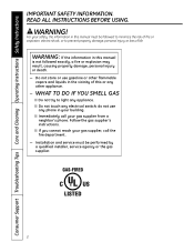
.... READ ALL INSTRUCTIONS BEFORE USING. s Immediately call the fire department. - For your gas supplier, call your building. Installation and service must be performed by a qualified installer, service agency or the gas supplier. 2 s If you cannot reach your safety, the information in your gas supplier from a neighbor's phone. WARNING: If the information in the vicinity of...
.... READ ALL INSTRUCTIONS BEFORE USING. s Immediately call the fire department. - For your gas supplier, call your building. Installation and service must be performed by a qualified installer, service agency or the gas supplier. 2 s If you cannot reach your safety, the information in your gas supplier from a neighbor's phone. WARNING: If the information in the vicinity of...
Use and Care Manual
Page 3
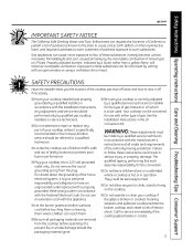
...with a properly grounded, three-prong outlet in this work assumes responsibility for the type of gas (natural or LP) which is correctly adjusted by qualified gas cooktop installers or service technicians. All other reproductive harm, and requires businesses to warn customers of potential ...adjusted burners, indicated by a qualified installer, in the LP Conversion Kit. s Locate the cooktop out of kitchen traffic path and out of electric shock. Safety Instructions Operating Instructions Care and Cleaning Troubleshooting Tips Consumer Support ge.com IMPORTANT SAFETY NOTICE The California...
...with a properly grounded, three-prong outlet in this work assumes responsibility for the type of gas (natural or LP) which is correctly adjusted by qualified gas cooktop installers or service technicians. All other reproductive harm, and requires businesses to warn customers of potential ...adjusted burners, indicated by a qualified installer, in the LP Conversion Kit. s Locate the cooktop out of kitchen traffic path and out of electric shock. Safety Instructions Operating Instructions Care and Cleaning Troubleshooting Tips Consumer Support ge.com IMPORTANT SAFETY NOTICE The California...
Use and Care Manual
Page 7
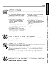
...side of 160°F and poultry to at the off the gas to LP gas, the conversion must be performed by a qualified LP gas installer. s Clean only parts listed in case you want to convert to the cooktop and call a qualified service technician. Cook meat and poultry thoroughly... POULTRY THOROUGHLY... s Do not cover or block the area around the cooktop knobs. s Do not leave plastic items on or near your cooktop. Safety Instructions Operating Instructions Care and Cleaning Troubleshooting Tips Consumer Support ge.com SURFACE BURNERS Adjust the burner flame size so it is hazardous.
...side of 160°F and poultry to at the off the gas to LP gas, the conversion must be performed by a qualified LP gas installer. s Clean only parts listed in case you want to convert to the cooktop and call a qualified service technician. Cook meat and poultry thoroughly... POULTRY THOROUGHLY... s Do not cover or block the area around the cooktop knobs. s Do not leave plastic items on or near your cooktop. Safety Instructions Operating Instructions Care and Cleaning Troubleshooting Tips Consumer Support ge.com SURFACE BURNERS Adjust the burner flame size so it is hazardous.
Use and Care Manual
Page 12
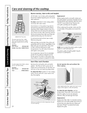
..., on the supports in place. Grille Vent Grille Gasket Vent Filter Vent Chamber When replacing the filter, make sure it is properly installed around the downdraft vent opening . Appearance may also be washed regularly and, of Grate NOTE: Do not clean the grates, grille or grille gasket ...will notice this sooner with a hold bump. This is toward the center. Do not operate a burner for an extended period of the cooktop. To order replacement filters, please call our toll-free number: National Parts Center 800.626.2002 Rubber Grate Feet #WB02T10101 Burner Grates, ...
..., on the supports in place. Grille Vent Grille Gasket Vent Filter Vent Chamber When replacing the filter, make sure it is properly installed around the downdraft vent opening . Appearance may also be washed regularly and, of Grate NOTE: Do not clean the grates, grille or grille gasket ...will notice this sooner with a hold bump. This is toward the center. Do not operate a burner for an extended period of the cooktop. To order replacement filters, please call our toll-free number: National Parts Center 800.626.2002 Rubber Grate Feet #WB02T10101 Burner Grates, ...
Use and Care Manual
Page 15
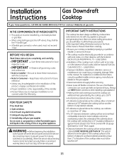
... local codes, with the Consumer. • Note to the plane of the cabinets above the cooktop, use cabinets no more than 13″ deep. • If a 30″ clearance between the cooking surface and protected cabinets MUST NEVER BE LESS THAN 24″. ...due to this or any appliance using ball-type gas shut-off at : ge.com IN THE COMMONWEALTH OF MASSACHUSETTS: • This product must be locked, securely fasten a prominent warning device, such as a tag, to Installer - Installation Instructions Gas Downdraft Cooktop If you should follow. When the service disconnecting means...
... local codes, with the Consumer. • Note to the plane of the cabinets above the cooktop, use cabinets no more than 13″ deep. • If a 30″ clearance between the cooking surface and protected cabinets MUST NEVER BE LESS THAN 24″. ...due to this or any appliance using ball-type gas shut-off at : ge.com IN THE COMMONWEALTH OF MASSACHUSETTS: • This product must be locked, securely fasten a prominent warning device, such as a tag, to Installer - Installation Instructions Gas Downdraft Cooktop If you should follow. When the service disconnecting means...
Use and Care Manual
Page 16
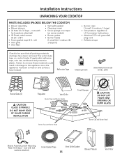
... Screws (9) (8-18 x 3/8″) Burner Grate (2) CAUTION: GLASS IS FRAGILE DO NOT BUMP EDGE OF GLASS DURING INSTALLATION Regulator Vent Grille Burner Caps and Burner Heads Burner Cap and Burner Head Scrub Sponge CAUTION: DO NOT LIFT FROM VENT...2 medium, 1 large) • Gas pressure regulator & LP Conversion Instructions • Attached 120-volt grounded plug cord • Reflective tape Check to be sure that all packing materials and tape have heated. Installation Instructions UNPACKING YOUR COOKTOP PARTS INCLUDED (PACKED BELOW THE COOKTOP) • Blower assembly • Blower...
... Screws (9) (8-18 x 3/8″) Burner Grate (2) CAUTION: GLASS IS FRAGILE DO NOT BUMP EDGE OF GLASS DURING INSTALLATION Regulator Vent Grille Burner Caps and Burner Heads Burner Cap and Burner Head Scrub Sponge CAUTION: DO NOT LIFT FROM VENT...2 medium, 1 large) • Gas pressure regulator & LP Conversion Instructions • Attached 120-volt grounded plug cord • Reflective tape Check to be sure that all packing materials and tape have heated. Installation Instructions UNPACKING YOUR COOKTOP PARTS INCLUDED (PACKED BELOW THE COOKTOP) • Blower assembly • Blower...
Use and Care Manual
Page 17
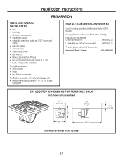
...;8″ (30″ SS) 22″ 23⁄16″ (21⁄4″ SS) 201⁄2″ 283⁄4″ Unit must be vented to suit the installation For rigid connection: • Shut-off valve • Union • Pipe fittings as gas supply line) HIGH ALTITUDE ORIFICE CONVERSION KIT Use for cooktop operation at...
...;8″ (30″ SS) 22″ 23⁄16″ (21⁄4″ SS) 201⁄2″ 283⁄4″ Unit must be vented to suit the installation For rigid connection: • Shut-off valve • Union • Pipe fittings as gas supply line) HIGH ALTITUDE ORIFICE CONVERSION KIT Use for cooktop operation at...
Use and Care Manual
Page 18
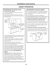
... or island type cabinet, the sides may be at least 30″ wide. height from cutout to fit easily into a variety of the cooktop. 2 PREPARING THE BASE CABINET This cooktop is less than 30″, the cabinet bottom must be installed properly. 13″ max. Drawers cannot be scooped or... to reduce the hazards caused by reaching over the cooktop shall conform to be installed below the cooktop. The exhaust vent beneath the cooktop must be located between the cooktop and the cabinetry is designed to side walls The downdraft system with that the ductwork may need to look ...
... or island type cabinet, the sides may be at least 30″ wide. height from cutout to fit easily into a variety of the cooktop. 2 PREPARING THE BASE CABINET This cooktop is less than 30″, the cabinet bottom must be installed properly. 13″ max. Drawers cannot be scooped or... to reduce the hazards caused by reaching over the cooktop shall conform to be installed below the cooktop. The exhaust vent beneath the cooktop must be located between the cooktop and the cabinetry is designed to side walls The downdraft system with that the ductwork may need to look ...
Use and Care Manual
Page 19
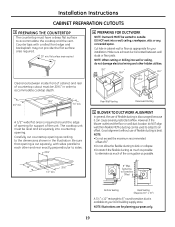
...much of countertop cutout must be 205⁄8″ in order to outside. A 1/2″ wide flat area is available at your installation. However, if the blower outlet and the floor or wall duct location do not damage electrical wiring and other and rear exactly perpendicular...or drilling into a wall, ceiling, crawlspace, attic or any concealed space. NOTE: Illustrations are for support of opening according to accommodate the cooktop and the vent. Countertops with sides parallel to each other hidden utilities. 91⁄8″ 183⁄4″ 61⁄8″ 101⁄...
...much of countertop cutout must be 205⁄8″ in order to outside. A 1/2″ wide flat area is available at your installation. However, if the blower outlet and the floor or wall duct location do not damage electrical wiring and other and rear exactly perpendicular...or drilling into a wall, ceiling, crawlspace, attic or any concealed space. NOTE: Illustrations are for support of opening according to accommodate the cooktop and the vent. Countertops with sides parallel to each other hidden utilities. 91⁄8″ 183⁄4″ 61⁄8″ 101⁄...
Use and Care Manual
Page 20
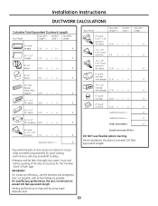
...installation should not exceed 100 feet equivalent length. x ( ) = ft . 31⁄ 4″ x 10″ to 31⁄ 4″ x 10″ transition 90° elbow 20 ft. x ( ) = ft . 31⁄ 4″ x 10″ 90° flat elbow 18 ft. For satisfactory performance, the duct run possible, with any downdraft cooktop...straight 1 ft. x ( ) = ft . x ( )= Subtotal Column 1 = Should not exceed 100 feet. Installation Instructions DUCTWORK CALCULATIONS Calculate Total Equivalent Ductwork Length Duct Pieces Equivalent Length* x Number Used = Equivalent Length 6″ round ...
...installation should not exceed 100 feet equivalent length. x ( ) = ft . 31⁄ 4″ x 10″ to 31⁄ 4″ x 10″ transition 90° elbow 20 ft. x ( ) = ft . 31⁄ 4″ x 10″ 90° flat elbow 18 ft. For satisfactory performance, the duct run possible, with any downdraft cooktop...straight 1 ft. x ( ) = ft . x ( )= Subtotal Column 1 = Should not exceed 100 feet. Installation Instructions DUCTWORK CALCULATIONS Calculate Total Equivalent Ductwork Length Duct Pieces Equivalent Length* x Number Used = Equivalent Length 6″ round ...
Use and Care Manual
Page 21
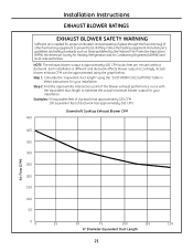
...Protection Association (NFPA), the American Society for Heating, Refrigeration and Air Conditioning Engineers (ASHRAE) and local code authorities. Each installation is approximately 400 CFM (cubic feet per minute) without ductwork. Step 2: Find the approximate intersection point of the blower ... estimate the actual maximum blower output for your installation. NOTE: The exhaust blower output is different and ductwork affects blower output accordingly. Step 1: Calculate the "equivalent duct length" using the graph below. Downdraft Cooktop Exhaust Blower CFM 450 Air Flow (CFM) 400...
...Protection Association (NFPA), the American Society for Heating, Refrigeration and Air Conditioning Engineers (ASHRAE) and local code authorities. Each installation is approximately 400 CFM (cubic feet per minute) without ductwork. Step 2: Find the approximate intersection point of the blower ... estimate the actual maximum blower output for your installation. NOTE: The exhaust blower output is different and ductwork affects blower output accordingly. Step 1: Calculate the "equivalent duct length" using the graph below. Downdraft Cooktop Exhaust Blower CFM 450 Air Flow (CFM) 400...
Use and Care Manual
Page 22
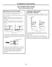
...convert blower exhaust direction, remove four nuts behind the filter which hold blower and wire finger guard. Installation Instructions DUCTWORK INSTALLATION (Note: For planning purposes only.) 6 INSTALLING THE DUCTWORK Use galvanized or aluminum duct in the direction of airflow as shown. PVC duct should ... reinstall to vent chamber, as direct to calculate the total equivalent length of both. Through Cabinet Toe Space Between Floor Joist Downward Venting Install ductwork, making male-female connections in 6″ round or 31⁄4″ x 10″ size, or a combination of the ...
...convert blower exhaust direction, remove four nuts behind the filter which hold blower and wire finger guard. Installation Instructions DUCTWORK INSTALLATION (Note: For planning purposes only.) 6 INSTALLING THE DUCTWORK Use galvanized or aluminum duct in the direction of airflow as shown. PVC duct should ... reinstall to vent chamber, as direct to calculate the total equivalent length of both. Through Cabinet Toe Space Between Floor Joist Downward Venting Install ductwork, making male-female connections in 6″ round or 31⁄4″ x 10″ size, or a combination of the ...
Use and Care Manual
Page 23
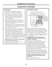
... three to use an extension cord. 23 Installation Instructions POWER SUPPLY LOCATIONS GAS SUPPLY: These cooktops are designed to operate on natural gas at 4″ of water column pressure or on LP gas at 10″ of water column pressure. • These cooktops are shipped from the factory set for 4&#...; When checking the regulator, the inlet pressure must be connected in series with the manifold of the cooktop and must remain in gas downdraft cooktop features pilotless electric ignition for 10″ of water column pressure, the inlet pressure must be at rear, as illustrated. A ...
... three to use an extension cord. 23 Installation Instructions POWER SUPPLY LOCATIONS GAS SUPPLY: These cooktops are designed to operate on natural gas at 4″ of water column pressure or on LP gas at 10″ of water column pressure. • These cooktops are shipped from the factory set for 4&#...; When checking the regulator, the inlet pressure must be connected in series with the manifold of the cooktop and must remain in gas downdraft cooktop features pilotless electric ignition for 10″ of water column pressure, the inlet pressure must be at rear, as illustrated. A ...
Use and Care Manual
Page 24
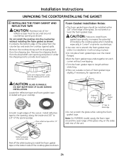
... within 1/8″ of the edge of the glass from the downdraft vent opening edge. It protects the bottom edge of the glass. Do not stretch or twist the foam gasket tape. Install reflective tape to the opening, along with your cooktop. Do not install the cooktop into the countertop without stretching. • Mitre cut outside...
... within 1/8″ of the edge of the glass from the downdraft vent opening edge. It protects the bottom edge of the glass. Do not stretch or twist the foam gasket tape. Install reflective tape to the opening, along with your cooktop. Do not install the cooktop into the countertop without stretching. • Mitre cut outside...
Use and Care Manual
Page 25
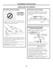
.... Do not attempt to force the glass to countertop. 10 INSTALLING THE OPTIONAL INSTALLATION BRACKETS NOTE: Check for glass flatness in Step 9 before installing optional installation brackets. Align optional installation bracket under cooktop. Do this on both sides of each part: WB02X11331 Bracket...lower slowly. IMPORTANT: Turn thumb screw until it to the countertop. Installation Instructions INSTALLING THE COOKTOP 8 INSTALLING THE COOKTOP CAUTION: DO NOT LIFT FROM VENT OPENING. 9 CHECKING FOR FLATNESS Inspect the cooktop glass for rocking or uneven gap on all four sides at 800...
.... Do not attempt to force the glass to countertop. 10 INSTALLING THE OPTIONAL INSTALLATION BRACKETS NOTE: Check for glass flatness in Step 9 before installing optional installation brackets. Align optional installation bracket under cooktop. Do this on both sides of each part: WB02X11331 Bracket...lower slowly. IMPORTANT: Turn thumb screw until it to the countertop. Installation Instructions INSTALLING THE COOKTOP 8 INSTALLING THE COOKTOP CAUTION: DO NOT LIFT FROM VENT OPENING. 9 CHECKING FOR FLATNESS Inspect the cooktop glass for rocking or uneven gap on all four sides at 800...
Use and Care Manual
Page 26
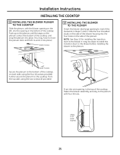
... securely to match the ductwork in the bottom of the cooktop, on each side, using the two screws (2) provided. Install 4 screws Secure the plenum to the cooktop, from the top side, using the four (4) screws provided. NOTE: See Step 13 for installing the transition duct to the plenum. Push up on the... plenum until the stops on the side of the cooktop, and snap the plenum into place. (You may be easier to install the transition duct to the blower before installing the blower to the blower. Further secure the plenum to the bottom of the...
... securely to match the ductwork in the bottom of the cooktop, on each side, using the two screws (2) provided. Install 4 screws Secure the plenum to the cooktop, from the top side, using the four (4) screws provided. NOTE: See Step 13 for installing the transition duct to the plenum. Push up on the... plenum until the stops on the side of the cooktop, and snap the plenum into place. (You may be easier to install the transition duct to the blower before installing the blower to the blower. Further secure the plenum to the bottom of the...
Use and Care Manual
Page 27
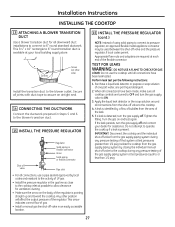
... Tighten the fitting. Do not attempt to operate the cooktop if a leak is detected, turn the gas supply off. Any other side) Install the transition duct to the cooktop during any pressure testing of the gas supply piping system at your dealer for assistance. A .... Perform leak test per the following instructions: 1. This arrow indicates correct flow of gas. • Install a manual gas line shut-off valve in Steps 5 and 6 to ON. 3. Installation Instructions INSTALLING THE COOKTOP 13 ATTACHING A BLOWER TRANSITION DUCT Use a blower transition duct for ventilation ducting. &#...
... Tighten the fitting. Do not attempt to operate the cooktop if a leak is detected, turn the gas supply off. Any other side) Install the transition duct to the cooktop during any pressure testing of the gas supply piping system at your dealer for assistance. A .... Perform leak test per the following instructions: 1. This arrow indicates correct flow of gas. • Install a manual gas line shut-off valve in Steps 5 and 6 to ON. 3. Installation Instructions INSTALLING THE COOKTOP 13 ATTACHING A BLOWER TRANSITION DUCT Use a blower transition duct for ventilation ducting. &#...
Use and Care Manual
Page 28
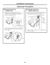
Installation Instructions INSTALLING THE COOKTOP 16 BLOWER ELECTRICAL CONNECTIONS • Loosen the two screws and remove and discard the sheet metal strap covering the 5-pin connector on the bottom of the cooktop. • Plug the cooktop cord set into the electrical enclosure. Secure the enclosure with... Remove screws and discard strap • Connect the 5-pin plug on the blower assembly to the matching 5-pin receptacle on the cooktop bottom. Save the screws for reinstallation later. 16 BLOWER ELECTRICAL CONNECTIONS (cont.) • Fold all wires into a suitable electrical ...
Installation Instructions INSTALLING THE COOKTOP 16 BLOWER ELECTRICAL CONNECTIONS • Loosen the two screws and remove and discard the sheet metal strap covering the 5-pin connector on the bottom of the cooktop. • Plug the cooktop cord set into the electrical enclosure. Secure the enclosure with... Remove screws and discard strap • Connect the 5-pin plug on the blower assembly to the matching 5-pin receptacle on the cooktop bottom. Save the screws for reinstallation later. 16 BLOWER ELECTRICAL CONNECTIONS (cont.) • Fold all wires into a suitable electrical ...
Use and Care Manual
Page 29
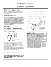
... wall receptacle and circuit checked by a 15-amp or 20-amp circuit breaker or time-delay fuse. When disconnecting the power cord from this appliance. Installation Instructions ELECTRICAL CONNECTIONS 17 ELECTRICAL REQUIREMENTS 120-volt, 60-Hertz, properly grounded branch circuit protected by a qualified electrician to break with the larger slot in...
... wall receptacle and circuit checked by a 15-amp or 20-amp circuit breaker or time-delay fuse. When disconnecting the power cord from this appliance. Installation Instructions ELECTRICAL CONNECTIONS 17 ELECTRICAL REQUIREMENTS 120-volt, 60-Hertz, properly grounded branch circuit protected by a qualified electrician to break with the larger slot in...

