
Use and Care Manual
Page 1
.... . . .4-9 Care and Cleaning Air Filter 11 Front Grille 10 Grille and Case 10 Outdoor Coils 10 Installation Instructions Before You Begin 12, 13 Installing a J-Model in an Existing Wall Case 14 Through-the-Wall Installation 15 Window Installation (Optional 16-21 Troubleshooting Tips 22 Normal Operating Sounds 22 Consumer Support Consumer Support Back Cover... française de ce manuel d'utilisation, veuillez visiter notre site web à l'adresse GEAppliances.com. As an ENERGY STAR® partner, GE has determined that this manual, visit our Website at GEAppliances.com.
.... . . .4-9 Care and Cleaning Air Filter 11 Front Grille 10 Grille and Case 10 Outdoor Coils 10 Installation Instructions Before You Begin 12, 13 Installing a J-Model in an Existing Wall Case 14 Through-the-Wall Installation 15 Window Installation (Optional 16-21 Troubleshooting Tips 22 Normal Operating Sounds 22 Consumer Support Consumer Support Back Cover... française de ce manuel d'utilisation, veuillez visiter notre site web à l'adresse GEAppliances.com. As an ENERGY STAR® partner, GE has determined that this manual, visit our Website at GEAppliances.com.

Use and Care Manual
Page 2
...or other flammable vapors or liquids in the vicinity of this Owner's Manual. ■ This air conditioner must be properly installed in this or any other appliance. ■ All air conditioners contain refrigerants, which under any repairs or cleaning. HOW...air conditioner by a qualified electrician to make sure the outlet is provided on the power cord. Consumer Support Troubleshooting Tips Installation Instructions Care and Cleaning Operating Instructions Safety Instructions IMPORTANT SAFETY INFORMATION. SAFETY PRECAUTIONS WARNING! A damaged power supply cord must be...
...or other flammable vapors or liquids in the vicinity of this Owner's Manual. ■ This air conditioner must be properly installed in this or any other appliance. ■ All air conditioners contain refrigerants, which under any repairs or cleaning. HOW...air conditioner by a qualified electrician to make sure the outlet is provided on the power cord. Consumer Support Troubleshooting Tips Installation Instructions Care and Cleaning Operating Instructions Safety Instructions IMPORTANT SAFETY INFORMATION. SAFETY PRECAUTIONS WARNING! A damaged power supply cord must be...

Use and Care Manual
Page 3
... connection of the 230/208-volt models. ■ If you must be 15 amperes (minimum) and 125 volts. Safety Instructions Operating Instructions Care and Cleaning Installation Instructions Troubleshooting Tips Consumer Support GEAppliances.com USE OF EXTENSION CORDS-115-Volt models only WARNING! USE OF ADAPTER PLUGS-115-Volt models only WARNING...
... connection of the 230/208-volt models. ■ If you must be 15 amperes (minimum) and 125 volts. Safety Instructions Operating Instructions Care and Cleaning Installation Instructions Troubleshooting Tips Consumer Support GEAppliances.com USE OF EXTENSION CORDS-115-Volt models only WARNING! USE OF ADAPTER PLUGS-115-Volt models only WARNING...

Use and Care Manual
Page 4
... air conditioner-Cool Only Models Appearance may vary. SLEEP Press to set the time in half hours up to 24 hours. Consumer Support Troubleshooting Tips Installation Instructions Care and Cleaning Operating Instructions Safety Instructions About the controls on the air conditioner control panel indicate the selected settings. Each touch will automatically...
... air conditioner-Cool Only Models Appearance may vary. SLEEP Press to set the time in half hours up to 24 hours. Consumer Support Troubleshooting Tips Installation Instructions Care and Cleaning Operating Instructions Safety Instructions About the controls on the air conditioner control panel indicate the selected settings. Each touch will automatically...

Use and Care Manual
Page 5
... and the LOW, MED or HIGH indicator light is used to provide air circulation and filtering without cooling. Safety Instructions Operating Instructions Care and Cleaning Installation Instructions Troubleshooting Tips Consumer Support GEAppliances.com COOL MODE Remote Control 1. A thermostat is lit for the desired fan speed. 5 Press COOL pad...
... and the LOW, MED or HIGH indicator light is used to provide air circulation and filtering without cooling. Safety Instructions Operating Instructions Care and Cleaning Installation Instructions Troubleshooting Tips Consumer Support GEAppliances.com COOL MODE Remote Control 1. A thermostat is lit for the desired fan speed. 5 Press COOL pad...
Use and Care Manual
Page 6
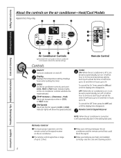
... is between the air conditioner and the remote control that could block the signal. ■ Make sure batteries are fresh and installed correctly-see the Care and Cleaning section. 6 Display Displays the temperature setting. Indicator lights will show the speed selected. FAN Speeds...selected. Indicator lights on and off in hours up to automatically turn off . Consumer Support Troubleshooting Tips Installation Instructions Care and Cleaning Operating Instructions Safety Instructions About the controls on the air conditioner control panel indicate the selected settings.
... is between the air conditioner and the remote control that could block the signal. ■ Make sure batteries are fresh and installed correctly-see the Care and Cleaning section. 6 Display Displays the temperature setting. Indicator lights will show the speed selected. FAN Speeds...selected. Indicator lights on and off in hours up to automatically turn off . Consumer Support Troubleshooting Tips Installation Instructions Care and Cleaning Operating Instructions Safety Instructions About the controls on the air conditioner control panel indicate the selected settings.

Use and Care Manual
Page 7
... fan speed. pads to begin . Press the INCREASE + / DECREASE - FAN Use the FAN to set level of comfort. Safety Instructions Operating Instructions Care and Cleaning Installation Instructions Troubleshooting Tips Consumer Support GEAppliances.com COOL MODE Remote Control 1. Press LOW or HIGH pads to provide air circulation and filtering without cooling or...
... fan speed. pads to begin . Press the INCREASE + / DECREASE - FAN Use the FAN to set level of comfort. Safety Instructions Operating Instructions Care and Cleaning Installation Instructions Troubleshooting Tips Consumer Support GEAppliances.com COOL MODE Remote Control 1. Press LOW or HIGH pads to provide air circulation and filtering without cooling or...

Use and Care Manual
Page 8
... switches and ensuring they are disabled. 8 The default setting is down . To open or close the vent: 1. Heat (on some models) Consumer Support Troubleshooting Tips Installation Instructions Care and Cleaning Operating Instructions Safety Instructions About the controls on the air conditioner Vent Control The vent control is located behind the room...
... switches and ensuring they are disabled. 8 The default setting is down . To open or close the vent: 1. Heat (on some models) Consumer Support Troubleshooting Tips Installation Instructions Care and Cleaning Operating Instructions Safety Instructions About the controls on the air conditioner Vent Control The vent control is located behind the room...

Use and Care Manual
Page 9
.... No line voltage connections should be in the enabled (UP) position to activate the remote thermostat. (See the installation instructions supplied with 24 VAC signal. Isolate all desired connections have been made to the electronics can result from line ...using a digital/electronic wall thermostat, ensure it is responsible for the wall thermostat. Safety Instructions Operating Instructions Care and Cleaning Installation Instructions Troubleshooting Tips Consumer Support GEAppliances.com Terminal Connections Remote Thermostat - Set aside screws and plastic cover. 3 To make ...
.... No line voltage connections should be in the enabled (UP) position to activate the remote thermostat. (See the installation instructions supplied with 24 VAC signal. Isolate all desired connections have been made to the electronics can result from line ...using a digital/electronic wall thermostat, ensure it is responsible for the wall thermostat. Safety Instructions Operating Instructions Care and Cleaning Installation Instructions Troubleshooting Tips Consumer Support GEAppliances.com Terminal Connections Remote Thermostat - Set aside screws and plastic cover. 3 To make ...

Use and Care Manual
Page 10
...model and serial numbers on the case and snap into place. Pull the filter out. 2. Grille Tab 10 Consumer Support Troubleshooting Tips Installation Instructions Care and Cleaning Operating Instructions Safety Instructions Care and cleaning of the case. Replace the screws and filter. Grille and Case ...the plug from the tabs on the front grille even with dirt or soot they may be professionally steam cleaned, a service available through your GE service outlet. Remove the two grille screws. 3. To clean, use bleach or abrasives. To remove: 1. Grille Tab On some models ...
...model and serial numbers on the case and snap into place. Pull the filter out. 2. Grille Tab 10 Consumer Support Troubleshooting Tips Installation Instructions Care and Cleaning Operating Instructions Safety Instructions Care and cleaning of the case. Replace the screws and filter. Grille and Case ...the plug from the tabs on the front grille even with dirt or soot they may be professionally steam cleaned, a service available through your GE service outlet. Remove the two grille screws. 3. To clean, use bleach or abrasives. To remove: 1. Grille Tab On some models ...

Use and Care Manual
Page 11
...: ■ Use 2 AAA (1.5 volt) batteries. Do not use rechargeable batteries. ■ Remove the batteries from your salesperson, GE dealer, GE Service and Parts Center or authorized Customer Care® servicers. Operating without the filter in the Remote Control 1 Remove the battery cover... (-) of premature component failure. If a filter becomes torn or damaged it back into position. Replacement filters are installed correctly. 3 Reattach the cover by pushing it should be used for a long time. 11 Safety Instructions Operating Instructions Care and Cleaning...
...: ■ Use 2 AAA (1.5 volt) batteries. Do not use rechargeable batteries. ■ Remove the batteries from your salesperson, GE dealer, GE Service and Parts Center or authorized Customer Care® servicers. Operating without the filter in the Remote Control 1 Remove the battery cover... (-) of premature component failure. If a filter becomes torn or damaged it back into position. Replacement filters are installed correctly. 3 Reattach the cover by pushing it should be used for a long time. 11 Safety Instructions Operating Instructions Care and Cleaning...

Use and Care Manual
Page 12
...the power cord. Aluminum house wiring may need a kit to properly adapt the case to Consumer - GE strongly recommends the removal of the old wall case and the installation of this air conditioner. What is also used with a properly grounded 3-prong wall outlet. There may... the wall case or "type" number to ensure proper airflow. 12 Keep these instructions with a properly grounded 3-prong outlet. Installation of a new GE Wall Case. If the wall outlet you be properly grounded. This is your responsibility and obligation to leave these instructions for the...
...the power cord. Aluminum house wiring may need a kit to properly adapt the case to Consumer - GE strongly recommends the removal of the old wall case and the installation of this air conditioner. What is also used with a properly grounded 3-prong wall outlet. There may... the wall case or "type" number to ensure proper airflow. 12 Keep these instructions with a properly grounded 3-prong outlet. Installation of a new GE Wall Case. If the wall outlet you be properly grounded. This is your responsibility and obligation to leave these instructions for the...

Use and Care Manual
Page 13
..., 37, 38, 46, 47 or 48 (J-Chassis) RAB36, 37, 38, 46, 47 or 48 (J-Chassis) DESCRIPTION: Standard wall case for window installation. Remove the existing case and replace. Kit for "J" model chassis. Adapts Whirlpool wall case to a "J" model chassis. Fits Whirlpool wall cases 257⁄...outdoor grille, use of the air conditioner and contact a qualified service technician. Fits all GE wall cases 26″W x 18″H x 24″D. Adapts GE wall case to a "J" model chassis. Installation Instructions Read these kits for all other brands not listed. Power cord may include a current...
..., 37, 38, 46, 47 or 48 (J-Chassis) RAB36, 37, 38, 46, 47 or 48 (J-Chassis) DESCRIPTION: Standard wall case for window installation. Remove the existing case and replace. Kit for "J" model chassis. Adapts Whirlpool wall case to a "J" model chassis. Fits Whirlpool wall cases 257⁄...outdoor grille, use of the air conditioner and contact a qualified service technician. Fits all GE wall cases 26″W x 18″H x 24″D. Adapts GE wall case to a "J" model chassis. Installation Instructions Read these kits for all other brands not listed. Power cord may include a current...

Use and Care Manual
Page 14
Installation Instructions INSTALLING A J-MODEL IN AN EXISTING WALL CASE Read these instructions completely and carefully. 1 REMOVE LOCKING PLATE ON FRONT LEFT SIDE Locking plate Remove screw 4 REINSTALL LOCKING ... opening for the power cord is secure. 14 Remove shipping pads (if present) 3 CAREFULLY SLIDE AIR CONDITIONER BACK INTO CASE Make sure that the case installation is on the unit does not touch the wall case and that the tubing on the bottom of the front grille.
Installation Instructions INSTALLING A J-MODEL IN AN EXISTING WALL CASE Read these instructions completely and carefully. 1 REMOVE LOCKING PLATE ON FRONT LEFT SIDE Locking plate Remove screw 4 REINSTALL LOCKING ... opening for the power cord is secure. 14 Remove shipping pads (if present) 3 CAREFULLY SLIDE AIR CONDITIONER BACK INTO CASE Make sure that the case installation is on the unit does not touch the wall case and that the tubing on the bottom of the front grille.

Use and Care Manual
Page 15
...Inside Top of the building. For the 230/208-volt models the cord length is 72″ to the right and 47″ to install a receptacle. extension out from dripping inside of the case) Plaster line Caulking (above the opening should be used in brick veneer and ...(on all 4 sides on the outside and inside the wall and down the outside wall. Lintel - The cord length for improved caulking. Installation Instructions INSTALLING THROUGH THE WALL Read these instructions completely and carefully. 1 PREPARE OPENING IN WALL Make certain a wall receptacle is available close to the hole ...
...Inside Top of the building. For the 230/208-volt models the cord length is 72″ to the right and 47″ to install a receptacle. extension out from dripping inside of the case) Plaster line Caulking (above the opening should be used in brick veneer and ...(on all 4 sides on the outside and inside the wall and down the outside wall. Lintel - The cord length for improved caulking. Installation Instructions INSTALLING THROUGH THE WALL Read these instructions completely and carefully. 1 PREPARE OPENING IN WALL Make certain a wall receptacle is available close to the hole ...

Use and Care Manual
Page 16
Installation Instructions WINDOW INSTALLATION-OPTIONAL WARNING! See the window opening dimensions to the right. • All supporting parts must be secured to firm wood, masonry or metal. • The ... are on the left) (holes are on the right) Type A (9) Type C (painted) (6) Type D (2) Type B (2) 1 WINDOW REQUIREMENTS • These instructions are for a standard double-hung window. Installation must be installed without the accordion panels if needed to modify them for a standard double-hung window. You will need to fit in a narrow window.
Installation Instructions WINDOW INSTALLATION-OPTIONAL WARNING! See the window opening dimensions to the right. • All supporting parts must be secured to firm wood, masonry or metal. • The ... are on the left) (holes are on the right) Type A (9) Type C (painted) (6) Type D (2) Type B (2) 1 WINDOW REQUIREMENTS • These instructions are for a standard double-hung window. Installation must be installed without the accordion panels if needed to modify them for a standard double-hung window. You will need to fit in a narrow window.

Use and Care Manual
Page 17
... the stool. Clips Remove screw E Pull the bottom corners of the air conditioner and slide it fits flush with nails or screws provided by the installer. 3 REMOVE AIR CONDITIONER FROM CASE A Remove the front grille. To adjust for this, attach a piece of the case. THICKNESS: To determine ... taped to the back of the air conditioner to allow the air conditioner to fit inside of the case, case, use the 2 short screws. Installation Instructions 2 STORM WINDOW REQUIREMENTS A storm window frame will keep it into the clips at a 45° angle, insert it from draining properly....
... the stool. Clips Remove screw E Pull the bottom corners of the air conditioner and slide it fits flush with nails or screws provided by the installer. 3 REMOVE AIR CONDITIONER FROM CASE A Remove the front grille. To adjust for this, attach a piece of the case. THICKNESS: To determine ... taped to the back of the air conditioner to allow the air conditioner to fit inside of the case, case, use the 2 short screws. Installation Instructions 2 STORM WINDOW REQUIREMENTS A storm window frame will keep it into the clips at a 45° angle, insert it from draining properly....

Use and Care Manual
Page 18
... Outside 133⁄8″ Stool 133⁄8″ Inside Sill Centerline Outside 123⁄8″ Stool 123⁄8″ Inside 5 INSTALL SILL SUPPORTS A Assemble the sill supports. Type B Type E Sill support Spacer mounting screws Type (A) Spacer Lock nut Adjusting bolt... than the standard hex-head bolt provided. • On wood sills use with 123⁄8″ marks. Sill Bolt Outside 18 Installation Instructions WINDOW INSTALLATION-OPTIONAL (cont.) 4 PREPARE WINDOW A Mark the centerline of the stool. Do not fully tighten the spacer mounting screws at this ...
... Outside 133⁄8″ Stool 133⁄8″ Inside Sill Centerline Outside 123⁄8″ Stool 123⁄8″ Inside 5 INSTALL SILL SUPPORTS A Assemble the sill supports. Type B Type E Sill support Spacer mounting screws Type (A) Spacer Lock nut Adjusting bolt... than the standard hex-head bolt provided. • On wood sills use with 123⁄8″ marks. Sill Bolt Outside 18 Installation Instructions WINDOW INSTALLATION-OPTIONAL (cont.) 4 PREPARE WINDOW A Mark the centerline of the stool. Do not fully tighten the spacer mounting screws at this ...
Use and Care Manual
Page 19
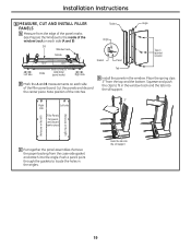
...) to the inside of the filler panel board. Cut the panels and discard the center piece. Gasket Angle Angle Gasket Panel Tab Type C (painted screws) D Install the panels in the window track and the tab into the sill support 19 Squeeze and push the clips to fit in the window. Push...
...) to the inside of the filler panel board. Cut the panels and discard the center piece. Gasket Angle Angle Gasket Panel Tab Type C (painted screws) D Install the panels in the window track and the tab into the sill support 19 Squeeze and push the clips to fit in the window. Push...

Use and Care Manual
Page 20
... vinyl window gasket over the brackets, even with a type D screw. 20 E With the window closed, mark where the window sash meets the case. Installation Instructions WINDOW INSTALLATION-OPTIONAL (cont.) 7 INSTALL CASE IN WINDOW A Peel off the backing from the bottom window gasket. Insert the panel tabs through the holes in the case line...
... vinyl window gasket over the brackets, even with a type D screw. 20 E With the window closed, mark where the window sash meets the case. Installation Instructions WINDOW INSTALLATION-OPTIONAL (cont.) 7 INSTALL CASE IN WINDOW A Peel off the backing from the bottom window gasket. Insert the panel tabs through the holes in the case line...


