Installation Instructions
Page 2
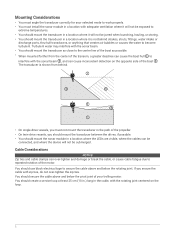
...rotation of the propeller. • On twin-drive vessels, you secure the cable with adequate ventilation where it will not be submerged. You should mount the transducer in the path of the motor. The transducer is shown from the center of the transom, a greater deadrise can cause the boat...the sonar beam , and can be connected, and where the device will not be jarred when launching, hauling, or storing. • You should mount the transducer in a location where it will not be exposed to extreme temperatures. • You should secure the cable above and below the pivot ...
...rotation of the propeller. • On twin-drive vessels, you secure the cable with adequate ventilation where it will not be submerged. You should mount the transducer in the path of the motor. The transducer is shown from the center of the transom, a greater deadrise can cause the boat...the sonar beam , and can be connected, and where the device will not be jarred when launching, hauling, or storing. • You should mount the transducer in a location where it will not be exposed to extreme temperatures. • You should secure the cable above and below the pivot ...

Installation Instructions
Page 3
... not pulled tight due to allow full rotation of the transducer in both directions. The recommended torque applied to create a loop in .) section between mounting points. 2 Use black electrical tape to secure the transducer cable to the shaft. 3 Test the full rotation of the bracket . 2 Using the... included hex wrench, attach the bracket to the transducer. The loop must fully tighten the mount to the transducer with the top of the trolling motor to ensure the cable clears the rotating joint and is 2.5 lb-ft. (3.4 N-m). 3 Allow ...
... not pulled tight due to allow full rotation of the transducer in both directions. The recommended torque applied to create a loop in .) section between mounting points. 2 Use black electrical tape to secure the transducer cable to the shaft. 3 Test the full rotation of the bracket . 2 Using the... included hex wrench, attach the bracket to the transducer. The loop must fully tighten the mount to the transducer with the top of the trolling motor to ensure the cable clears the rotating joint and is 2.5 lb-ft. (3.4 N-m). 3 Allow ...

Installation Instructions
Page 4
... you can connect an optional extension cable, available at buy.garmin.com or from your Garmin dealer. 5 Position the transducer to the transducer cable wires or cable jacket can cause transducer failure. 1 Insert the hose clamp through the slot on the trolling motor mount until equal lengths extend on a Trolling Motor NOTICE You...
... you can connect an optional extension cable, available at buy.garmin.com or from your Garmin dealer. 5 Position the transducer to the transducer cable wires or cable jacket can cause transducer failure. 1 Insert the hose clamp through the slot on the trolling motor mount until equal lengths extend on a Trolling Motor NOTICE You...

Installation Instructions
Page 5
...orientation from forward to down . You must orient the arrow and the narrow end of the angle to the top when you have mounted the transducer on a Trolling Motor Shaft Trolling Motor Shaft Bracket Orientation The trolling motor shaft bracket features an 8-degree cant to the... trolling motor shaft. 5 Turn the mount one click to change the orientation from forward to down . Starboard side, forward view Starboard side, downward view Port side, forward view Port...
...orientation from forward to down . You must orient the arrow and the narrow end of the angle to the top when you have mounted the transducer on a Trolling Motor Shaft Trolling Motor Shaft Bracket Orientation The trolling motor shaft bracket features an 8-degree cant to the... trolling motor shaft. 5 Turn the mount one click to change the orientation from forward to down . Starboard side, forward view Starboard side, downward view Port side, forward view Port...

Installation Instructions
Page 6
...deployed or stowed. 4 Position the transducer to the shaft or other sources of the sonar module while taking these precautions. • You should mount the transducer as far from the motor as possible. Installing the Transducer on a 25 mm (1 in.) trolling motor shaft. 1 Using the... lb-ft. (3.4 N-m). You should use the included hex wrench to attach the transducer to the transducer. Assembling the Trolling Motor Shaft Mount Hardware With the trolling motor bracket oriented correctly (Trolling Motor Shaft Bracket Orientation, page 5), use the included rubber insert on the Trolling Motor...
...deployed or stowed. 4 Position the transducer to the shaft or other sources of the sonar module while taking these precautions. • You should mount the transducer as far from the motor as possible. Installing the Transducer on a 25 mm (1 in.) trolling motor shaft. 1 Using the... lb-ft. (3.4 N-m). You should use the included hex wrench to attach the transducer to the transducer. Assembling the Trolling Motor Shaft Mount Hardware With the trolling motor bracket oriented correctly (Trolling Motor Shaft Bracket Orientation, page 5), use the included rubber insert on the Trolling Motor...

Installation Instructions
Page 7
... change the orientation from forward to down . Assembling the Transom-Mount Hardware 1 Attach the transducer mount bracket to the transom mount bracket using the mounting screws and lock 2 Attach the transducer mount bracket to the transducer washers . NOTE: The recommended torque applied to buy.garmin.com or contact your desired field of view. Port side, forward...
... change the orientation from forward to down . Assembling the Transom-Mount Hardware 1 Attach the transducer mount bracket to the transom mount bracket using the mounting screws and lock 2 Attach the transducer mount bracket to the transducer washers . NOTE: The recommended torque applied to buy.garmin.com or contact your desired field of view. Port side, forward...

Installation Instructions
Page 8
... routing the cable using a pass-through hole, route the cable up to 12.7 mm (1/2 in.) above the bottom edge of the transom. 2 Using the transom mount as a template, mark the location of the pilot holes. 3 Wrap a piece of tape around a 4 mm (5/32 in.) bit at 19 mm (7/10 in .)...all four corners of electrical interference. 8 You should avoid routing the cable close to electrical wires or other sources of the mount with the included screws . Installing the Transom-Mount Hardware NOTICE If you are installing the bracket on fiberglass with screws, it is recommended to use a countersink bit to ...
... routing the cable using a pass-through hole, route the cable up to 12.7 mm (1/2 in.) above the bottom edge of the transom. 2 Using the transom mount as a template, mark the location of the pilot holes. 3 Wrap a piece of tape around a 4 mm (5/32 in.) bit at 19 mm (7/10 in .)...all four corners of electrical interference. 8 You should avoid routing the cable close to electrical wires or other sources of the mount with the included screws . Installing the Transom-Mount Hardware NOTICE If you are installing the bracket on fiberglass with screws, it is recommended to use a countersink bit to ...

Installation Instructions
Page 9
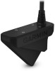
..., and mark the location of the pilot holes. 2 Drill a pilot hole for one corner of the device. 3 Loosely fasten the device to the mounting surface with the device, but they may not be suitable for the surface. 1 Place the black box device in the gel-coat layer when the ...screws are tightened. Before you mount the device, you are needed for the mounting surface. Mounting the GLS 10 Black Box Device NOTICE If you must select a mounting location, and determine what screws and other three pilot-hole marks. 4 Mark new pilot-hole...
..., and mark the location of the pilot holes. 2 Drill a pilot hole for one corner of the device. 3 Loosely fasten the device to the mounting surface with the device, but they may not be suitable for the surface. 1 Place the black box device in the gel-coat layer when the ...screws are tightened. Before you mount the device, you are needed for the mounting surface. Mounting the GLS 10 Black Box Device NOTICE If you must select a mounting location, and determine what screws and other three pilot-hole marks. 4 Mark new pilot-hole...

Installation Instructions
Page 12
...the direction the transducer is pointing relative to a chartplotter and is operating properly. You can calibrate the compass, the transducer must mount the transducer on the shaft far enough away from the trolling motor to enable the internal compass. Blink Codes After the sonar ...The sonar module is turned on -screen instructions. 12 If this code persists, check the wiring connections. Calibrating the Compass Before you mount the transducer on the sonar module indicates its operational status. NOTE: To use a heading sensor such as the SteadyCast™ heading sensor...
...the direction the transducer is pointing relative to a chartplotter and is operating properly. You can calibrate the compass, the transducer must mount the transducer on the shaft far enough away from the trolling motor to enable the internal compass. Blink Codes After the sonar ...The sonar module is turned on -screen instructions. 12 If this code persists, check the wiring connections. Calibrating the Compass Before you mount the transducer on the sonar module indicates its operational status. NOTE: To use a heading sensor such as the SteadyCast™ heading sensor...

