Installation Manual
Page 3
... on any and all related marks and logos are registered trademarks owned by Bluetooth SIG, Inc. References to GDL 5XR in this installation manual refer to the Garmin GDL 51R and GDL 52R unless specifically noted otherwise. Sirius, XM, SiriusXM, and all reproductions in whole or in the USA and ... the State of Google Inc. NOTE The Bluetooth® word mark and logos are trademarks of this installation manual refer to the Garmin GDL 51 and GDL 52 unless specifically noted otherwise. iPad®, iPhone®, iPod®, and iPod touch are the property of Apple Inc., registered in...
... on any and all related marks and logos are registered trademarks owned by Bluetooth SIG, Inc. References to GDL 5XR in this installation manual refer to the Garmin GDL 51R and GDL 52R unless specifically noted otherwise. Sirius, XM, SiriusXM, and all reproductions in whole or in the USA and ... the State of Google Inc. NOTE The Bluetooth® word mark and logos are trademarks of this installation manual refer to the Garmin GDL 51 and GDL 52 unless specifically noted otherwise. iPad®, iPhone®, iPod®, and iPod touch are the property of Apple Inc., registered in...
Installation Manual
Page 6
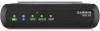
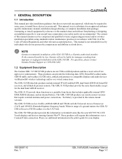
...for damages resulting from improper or negligent installation of a ground station, the GDL 52/ 52R will not be required in some cases, to this manual assumes use by a Garmin-authorized installer. The GDL 52/52R receives Traffic (ADS-B/ADS-R and TIS-B) on both Universal Access Transceiver ...wireless technology and/or over a Connext® data connection. For questions, please contact Garmin Product Support at 1-888-606-5482. 1.2 Equipment Description The Garmin GDL 51/51R/52/52R products are remote mount versions that includes applicable internal GPS/ SXM/ADS-B antennas, ...
...for damages resulting from improper or negligent installation of a ground station, the GDL 52/ 52R will not be required in some cases, to this manual assumes use by a Garmin-authorized installer. The GDL 52/52R receives Traffic (ADS-B/ADS-R and TIS-B) on both Universal Access Transceiver ...wireless technology and/or over a Connext® data connection. For questions, please contact Garmin Product Support at 1-888-606-5482. 1.2 Equipment Description The Garmin GDL 51/51R/52/52R products are remote mount versions that includes applicable internal GPS/ SXM/ADS-B antennas, ...
Installation Manual
Page 7
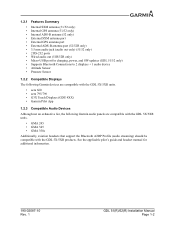
...; External ADS-B antenna port (52/52R only) • 3.5 mm audio jack (audio out only) (51/52 only) • 2 RS-232 ports • Wired audio out (51R/52R only) • Micro-USB port for additional information. 190-02087-10 Rev. 1 GDL 51(R)/52(R) Installation Manual Page 1-2 See ... headset manual for charging, power, and SW updates (GDL 51/52 only) • Supports Bluetooth Connections to 2 displays + 1 audio device • Attitude Sensor • Pressure Sensor 1.2.2 Compatible Displays The following Garmin devices are compatible with the GDL 5X/5XR units. • aera 660 • ...
...; External ADS-B antenna port (52/52R only) • 3.5 mm audio jack (audio out only) (51/52 only) • 2 RS-232 ports • Wired audio out (51R/52R only) • Micro-USB port for additional information. 190-02087-10 Rev. 1 GDL 51(R)/52(R) Installation Manual Page 1-2 See ... headset manual for charging, power, and SW updates (GDL 51/52 only) • Supports Bluetooth Connections to 2 displays + 1 audio device • Attitude Sensor • Pressure Sensor 1.2.2 Compatible Displays The following Garmin devices are compatible with the GDL 5X/5XR units. • aera 660 • ...
Installation Manual
Page 8
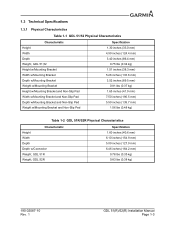
... inches (38.3 mm) 5.26 inches (133.6 mm) 3.52 inches (89.5 mm) 0.81 lbs (0.37 kg) 1.65 inches (41.9 mm) 7.50 inches (190.5 mm) 5.50 inches (139.7 mm) 1.06 lbs (0.48 kg) Table 1-2 GDL 51R/52R Physical Characteristics Characteristic Height Width Depth Depth w/Connector Weight, GDL 51R Weight, GDL 52R Specification 1.60 inches (40.6 mm) 6.10 inches...
... inches (38.3 mm) 5.26 inches (133.6 mm) 3.52 inches (89.5 mm) 0.81 lbs (0.37 kg) 1.65 inches (41.9 mm) 7.50 inches (190.5 mm) 5.50 inches (139.7 mm) 1.06 lbs (0.48 kg) Table 1-2 GDL 51R/52R Physical Characteristics Characteristic Height Width Depth Depth w/Connector Weight, GDL 51R Weight, GDL 52R Specification 1.60 inches (40.6 mm) 6.10 inches...
Installation Manual
Page 10
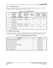
... P/N 190-01115-01 190-01194-00 190-01501-00 190-01532-00 190-01754-00 190-02017-20 190-02087-00 190-02087-10 Rev. 1 GDL 51(R)/52(R) Installation Manual Page 1-5 Unit Off, Charg- Unit On, Not Charging 0.17A @14V 0.09A @ 28V 0.16A @ 14V 0.09A @ 28V 0.27A @ .../5XR Reference Documents Document G3X/G3X Touch Installation Manual aera 795/796 Pilot's Guide Garmin Pilot User's Guide User's Guide, Garmin Pilot for the GDL 5X/5XR units. Power Specifications Unit GDL 51 GDL 51R GDL 52 GDL 52R Aircraft Power - Unit On 0.4 A @ 5V NA 0.67A @ 5V NA USB Power - Table 1-4. ing 0.82A @ 14V 0....
... P/N 190-01115-01 190-01194-00 190-01501-00 190-01532-00 190-01754-00 190-02017-20 190-02087-00 190-02087-10 Rev. 1 GDL 51(R)/52(R) Installation Manual Page 1-5 Unit Off, Charg- Unit On, Not Charging 0.17A @14V 0.09A @ 28V 0.16A @ 14V 0.09A @ 28V 0.27A @ .../5XR Reference Documents Document G3X/G3X Touch Installation Manual aera 795/796 Pilot's Guide Garmin Pilot User's Guide User's Guide, Garmin Pilot for the GDL 5X/5XR units. Power Specifications Unit GDL 51 GDL 51R GDL 52 GDL 52R Aircraft Power - Unit On 0.4 A @ 5V NA 0.67A @ 5V NA USB Power - Table 1-4. ing 0.82A @ 14V 0....
Installation Manual
Page 11
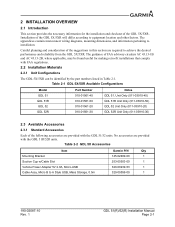
... diagrams, mounting dimensions, and information pertaining to A Style USB, Mass Storage, 0.5m Garmin P/N Qty 145-02489-00 1 253-00503-00 1 320-00239-53 1 320-00559-00 1 190-02087-10 Rev. 1 GDL 51(R)/52(R) Installation Manual Page 2-1 The guidance of FAA advisory circulars AC 43.13-1B and ... the GDL 51/52 units. Table 2-1 GDL 5X/5XR Available Configurations Model GDL 51 GDL 51R GDL 52 GDL 52R Part Number 010-01561-40 010-01561-50 010-01561-20 010-01561-30 Notes GDL 51, Unit Only (011-03910-40) GDL 51R Unit Only (011-03910-50) GDL 52 Unit Only (011-03910-20) GDL 52R Unit Only...
... diagrams, mounting dimensions, and information pertaining to A Style USB, Mass Storage, 0.5m Garmin P/N Qty 145-02489-00 1 253-00503-00 1 320-00239-53 1 320-00559-00 1 190-02087-10 Rev. 1 GDL 51(R)/52(R) Installation Manual Page 2-1 The guidance of FAA advisory circulars AC 43.13-1B and ... the GDL 51/52 units. Table 2-1 GDL 5X/5XR Available Configurations Model GDL 51 GDL 51R GDL 52 GDL 52R Part Number 010-01561-40 010-01561-50 010-01561-20 010-01561-30 Notes GDL 51, Unit Only (011-03910-40) GDL 51R Unit Only (011-03910-50) GDL 52 Unit Only (011-03910-20) GDL 52R Unit Only...
Installation Manual
Page 12
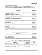
...kit (010-12498-60) and mounting hardware (not provided) are provided separately from the GDL 51R/52R units. Table 2-3 GDL 51/52 Available Accessories Equipment MCX to BNC Adapter Cable AC Adapter Cable, Micro B Cable Assembly, Data/Power (GDL Bare Wire) Cable Assembly, Data/Power with Mount (aera 795/796) Cable Assembly,... 010-12498-40 010-11270-00 010-10702-00 010-10052-02 Table 2-4 GDL 51R/52R Available Accessories Equipment GA 25 BNC Remote GPS Antenna (Low Profile) GA 24 TNC SXM Antenna GDL 51R/52R Connector Kit Garmin P/N 010-10701-00 010-12498-50 010-12498-60 Table 2-5 Contents of...
...kit (010-12498-60) and mounting hardware (not provided) are provided separately from the GDL 51R/52R units. Table 2-3 GDL 51/52 Available Accessories Equipment MCX to BNC Adapter Cable AC Adapter Cable, Micro B Cable Assembly, Data/Power (GDL Bare Wire) Cable Assembly, Data/Power with Mount (aera 795/796) Cable Assembly,... 010-12498-40 010-11270-00 010-10702-00 010-10052-02 Table 2-4 GDL 51R/52R Available Accessories Equipment GA 25 BNC Remote GPS Antenna (Low Profile) GA 24 TNC SXM Antenna GDL 51R/52R Connector Kit Garmin P/N 010-10701-00 010-12498-50 010-12498-60 Table 2-5 Contents of...
Installation Manual
Page 17
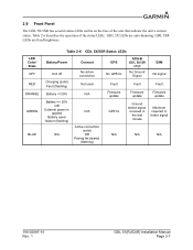
.../5XR has several status LEDs visible on the face of the status LEDs. LED Color/ State OFF RED ORANGE GREEN BLUE Table 2-6 GDL 5X/5XR Status LEDs Battery/Power Connext Unit off Charging (solid) Fault (flashing) No active connection Not used Battery = 20% OR ...Battery saver feature (flashing) N/A N/A Active connection (solid) OR Pairing list cleared (flashing) GPS No GPS fix Fault Firmware update GPS fix ADS-B (GDL 52/52R only) No Ground Signal SXM No signal Fault Fault Firmware update Firmware update Ground station signal received in the last minute Minimum required or better...
.../5XR has several status LEDs visible on the face of the status LEDs. LED Color/ State OFF RED ORANGE GREEN BLUE Table 2-6 GDL 5X/5XR Status LEDs Battery/Power Connext Unit off Charging (solid) Fault (flashing) No active connection Not used Battery = 20% OR ...Battery saver feature (flashing) N/A N/A Active connection (solid) OR Pairing list cleared (flashing) GPS No GPS fix Fault Firmware update GPS fix ADS-B (GDL 52/52R only) No Ground Signal SXM No signal Fault Fault Firmware update Firmware update Ground station signal received in the last minute Minimum required or better...
Installation Manual
Page 20
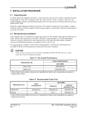
...interconnect wiring diagrams. Construct the actual harnesses in accordance with the connector kit. Table 3-1. All electrical connections to the GDL 51R/52R are subject to change without notice Table 3-2 Recommended Crimp Tools Manufacturer [1] Hand Crimping Tool 20-24 AWG Positioner ... M22520/2-08 M81969/1-04 Daniels N/A K13-1 M81969/1-04 [1] Non-Garmin part numbers shown are not maintained by Garmin and consequently are subject to change without notice. 190-02087-10 Rev. 1 GDL 51(R)/52(R) Installation Manual Page 3-1 Pin Contact Part Numbers Manufacturer [1] 15-...
...interconnect wiring diagrams. Construct the actual harnesses in accordance with the connector kit. Table 3-1. All electrical connections to the GDL 51R/52R are subject to change without notice Table 3-2 Recommended Crimp Tools Manufacturer [1] Hand Crimping Tool 20-24 AWG Positioner ... M22520/2-08 M81969/1-04 Daniels N/A K13-1 M81969/1-04 [1] Non-Garmin part numbers shown are not maintained by Garmin and consequently are subject to change without notice. 190-02087-10 Rev. 1 GDL 51(R)/52(R) Installation Manual Page 3-1 Pin Contact Part Numbers Manufacturer [1] 15-...
Installation Manual
Page 22
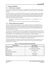
...typically performs better when a ground plane is typically made by connecting an external antenna via a cable connection to a Garmin Aera 660/795/796 or GDU 4XX display. Garmin recommends the antennas shown in Table 3-3 will work with any equivalent antenna that also meet the VSWR specification. 3.7.2... 4.00 dB 50 Ω 4.5 to 6.5 VDC up to the GDL 52 via the MCX connector. The GDL 52R requires an external ADS-B antenna for GPS/SXM antennas. The antenna should be mounted on the GDL 52R. The GDL 5X/5XR can receive GPS position information using the unit's internal antenna ...
...typically performs better when a ground plane is typically made by connecting an external antenna via a cable connection to a Garmin Aera 660/795/796 or GDU 4XX display. Garmin recommends the antennas shown in Table 3-3 will work with any equivalent antenna that also meet the VSWR specification. 3.7.2... 4.00 dB 50 Ω 4.5 to 6.5 VDC up to the GDL 52 via the MCX connector. The GDL 52R requires an external ADS-B antenna for GPS/SXM antennas. The antenna should be mounted on the GDL 52R. The GDL 5X/5XR can receive GPS position information using the unit's internal antenna ...
Installation Manual
Page 28
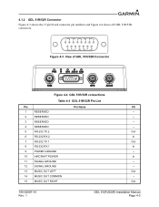
... Figure 4-3 shows the 15 pin D-sub connector pin numbers and Figure 4-4 shows all GDL 51R/52R connectors. Figure 4-3 View of GDL 51R/52R Connector Figure 4-4 GDL 51R/52R connections Table 4-3 GDL 51R/52R Pin List Pin Pin Name I/O 1 RESERVED -- 2 RESERVED -- 3 RESERVED -- 4 RESERVED -- 5 RS-232 TX 2 Out 6 RS-232 RX 2 In 7 RS-232 TX 1 Out 8 RS-232 RX 1 In... In 11 SIGNAL GROUND -- 12 SIGNAL GROUND -- 13 MUSIC OUT LEFT Out 14 MUSIC OUT COMMON -- 15 MUSIC OUT RIGHT Out 190-02087-10 Rev. 1 GDL 51(R)/52(R) Installation Manual Page 4-3
... Figure 4-3 shows the 15 pin D-sub connector pin numbers and Figure 4-4 shows all GDL 51R/52R connectors. Figure 4-3 View of GDL 51R/52R Connector Figure 4-4 GDL 51R/52R connections Table 4-3 GDL 51R/52R Pin List Pin Pin Name I/O 1 RESERVED -- 2 RESERVED -- 3 RESERVED -- 4 RESERVED -- 5 RS-232 TX 2 Out 6 RS-232 RX 2 In 7 RS-232 TX 1 Out 8 RS-232 RX 1 In... In 11 SIGNAL GROUND -- 12 SIGNAL GROUND -- 13 MUSIC OUT LEFT Out 14 MUSIC OUT COMMON -- 15 MUSIC OUT RIGHT Out 190-02087-10 Rev. 1 GDL 51(R)/52(R) Installation Manual Page 4-3
Installation Manual
Page 29
... TNC connector, see Section 3.9 for compatible antennas. 4.1.2.6 ADS-B Antenna Connection The GDL 52R ADS-B antenna connection uses a BNC connector, see Section 3.7.1 for compatible antennas. 190-02087-10 Rev. 1 GDL 51(R)/52(R) Installation Manual Page 4-4 It is recommended that a 3 Amp fuse or circuit breaker... be used to supply power to the GDL 5XR. 4.1.2.2 GDL 51R/52R RS-232 Electrical Characteristics The RS-232 outputs conform to ...
... TNC connector, see Section 3.9 for compatible antennas. 4.1.2.6 ADS-B Antenna Connection The GDL 52R ADS-B antenna connection uses a BNC connector, see Section 3.7.1 for compatible antennas. 190-02087-10 Rev. 1 GDL 51(R)/52(R) Installation Manual Page 4-4 It is recommended that a 3 Amp fuse or circuit breaker... be used to supply power to the GDL 5XR. 4.1.2.2 GDL 51R/52R RS-232 Electrical Characteristics The RS-232 outputs conform to ...
Installation Manual
Page 33
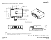
... A OUTLINE AND INSTALLATION DRAWINGS .828 21.04 2X 4.500 114.30 2X 2.250 57.15 6X .156 3.96 NOTE 4 3X 4.430 112.5 GDL 51R=2.80[71.1] GDL 52R=2.85 72.4 C.O.G. NOTE 3 6.16 156.4 5.00 127.0 6.46 164.2 .12 3.0 NOTES: 1. DIMENSIONS ARE NOMINAL AND TOLERANCES ARE NOT IMPLIED ...[mm]. CENTER OF GRAVITY (C.O.G.) LOCATION SHOWN IS WITHOUT CONNECTOR KIT INSTALLED. 4. NOTE 3 CONNECTOR SHOWN BROKEN OUT TO REVEAL MOUNTING HOLE GDL 52R SHOWN 1.63 41.4 .88 22.4 C.O.G. Figure A-2.1 GDL 51R/52R Outline and Installation Drawing 190-02087-10 Rev. 1 GDL 51(R)/52(R) Installation Manual Page A-4
... A OUTLINE AND INSTALLATION DRAWINGS .828 21.04 2X 4.500 114.30 2X 2.250 57.15 6X .156 3.96 NOTE 4 3X 4.430 112.5 GDL 51R=2.80[71.1] GDL 52R=2.85 72.4 C.O.G. NOTE 3 6.16 156.4 5.00 127.0 6.46 164.2 .12 3.0 NOTES: 1. DIMENSIONS ARE NOMINAL AND TOLERANCES ARE NOT IMPLIED ...[mm]. CENTER OF GRAVITY (C.O.G.) LOCATION SHOWN IS WITHOUT CONNECTOR KIT INSTALLED. 4. NOTE 3 CONNECTOR SHOWN BROKEN OUT TO REVEAL MOUNTING HOLE GDL 52R SHOWN 1.63 41.4 .88 22.4 C.O.G. Figure A-2.1 GDL 51R/52R Outline and Installation Drawing 190-02087-10 Rev. 1 GDL 51(R)/52(R) Installation Manual Page A-4
Installation Manual
Page 34
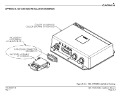
APPENDIX A OUTLINE AND INSTALLATION DRAWINGS GDL 51R 011-03910-50 GDL 52R (SHOWN) 011-03910-30 INCLUDED IN 010-12498-60 CONNECTOR KIT 15 PIN D-SUB CONNECTOR 330-00625-15 BACKSHELL ASSEMBLY 011-01855-01 190-02087-10 Rev. 1 Figure A-2.2 GDL 51R/52R Installation Drawing GDL 51(R)/52(R) Installation Manual Page A-5
APPENDIX A OUTLINE AND INSTALLATION DRAWINGS GDL 51R 011-03910-50 GDL 52R (SHOWN) 011-03910-30 INCLUDED IN 010-12498-60 CONNECTOR KIT 15 PIN D-SUB CONNECTOR 330-00625-15 BACKSHELL ASSEMBLY 011-01855-01 190-02087-10 Rev. 1 Figure A-2.2 GDL 51R/52R Installation Drawing GDL 51(R)/52(R) Installation Manual Page A-5