Product Manual
Page 4
... of conflict between this manual and any packaging part of China This product is not marked on any referenced document, this product. Related Standards Product specifications and functions described in GB18455-2001 is shipped as a component to manufacture the final products.
... of conflict between this manual and any packaging part of China This product is not marked on any referenced document, this product. Related Standards Product specifications and functions described in GB18455-2001 is shipped as a component to manufacture the final products.
Product Manual
Page 5
...MBA3147RC, and MBA3073RC 3.5 - inch hard disk drives with an embedded Serial Attached SCSI (SAS). Overview of Manual This manual consists of the disk drive. This chapter also describes diagnostic methods for error analysis and how analyze collected error information. Chapter 5 Installation This chapter explains how to install the disk drives. This manual details the specifications... a basic understanding of the disk drives and their use the other manuals. Chapter 2 Specifications This chapter gives detailed specifications of hard disk drives and their installation environment.
...MBA3147RC, and MBA3073RC 3.5 - inch hard disk drives with an embedded Serial Attached SCSI (SAS). Overview of Manual This manual consists of the disk drive. This chapter also describes diagnostic methods for error analysis and how analyze collected error information. Chapter 5 Installation This chapter explains how to install the disk drives. This manual details the specifications... a basic understanding of the disk drives and their use the other manuals. Chapter 2 Specifications This chapter gives detailed specifications of hard disk drives and their installation environment.

Product Manual
Page 9
Data Format 4. Installation 6. Parameter Data Format 6. Command Specifications 5. Specifications 3. Error Analysis 1. Command Processing 3. Sense Data and Error Recovery Methods 7. MANUAL ORGANIZATION PRODUCT MANUAL (This manual) SAS INTERFACE MANUAL 1. Disk Media Management C141-E252 5 SAS Interface 2. Data Buffer Management 4. Installation Requirements 5. General Description 2. Diagnostics and Maintenance 7.
Data Format 4. Installation 6. Parameter Data Format 6. Command Specifications 5. Specifications 3. Error Analysis 1. Command Processing 3. Sense Data and Error Recovery Methods 7. MANUAL ORGANIZATION PRODUCT MANUAL (This manual) SAS INTERFACE MANUAL 1. Disk Media Management C141-E252 5 SAS Interface 2. Data Buffer Management 4. Installation Requirements 5. General Description 2. Diagnostics and Maintenance 7.
Product Manual
Page 16
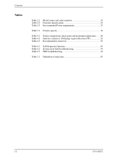
Contents Tables Table 2.1 Model names and order numbers 19 Table 2.2 Function specifications 20 Table 2.3 Environmental/Power requirements 23 Table 3.1 Format capacity 34 Table 4.1 Surface temperature check point and maximum temperature ....... 46 Table 4.2 Interface connector (SAS plug) signal allocation:CN1 52 Table 4.3 Recommended connectors 53 Table 6.1 Self-diagnostic functions 65 Table 6.2 System-level field troubleshooting 75 Table 6.3 HDD troubleshooting 76 Table 7.1 Definition of sense data 83 12 C141-E252
Contents Tables Table 2.1 Model names and order numbers 19 Table 2.2 Function specifications 20 Table 2.3 Environmental/Power requirements 23 Table 3.1 Format capacity 34 Table 4.1 Surface temperature check point and maximum temperature ....... 46 Table 4.2 Interface connector (SAS plug) signal allocation:CN1 52 Table 4.3 Recommended connectors 53 Table 6.1 Self-diagnostic functions 65 Table 6.2 System-level field troubleshooting 75 Table 6.3 HDD troubleshooting 76 Table 7.1 Definition of sense data 83 12 C141-E252
Product Manual
Page 23
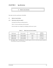
... type Capacity (user area) MBA3300RC CA06778-B400 SAS 300 GB (*) MBA3147RC CA06778-B200 SAS 147 GB (*) MBA3073RC CA06778-B100 SAS 73.5 GB (*) (*) One gigabyte (GB) = one billion bytes; accessible capacity will be changed by reinitializing with the user's system. CHAPTER 2 Specifications 2.1 Hardware Specifications This chapter describes specifications of the HDDs. 2.1 Hardware Specifications 2.1.1 Model name and order number Each model has...
... type Capacity (user area) MBA3300RC CA06778-B400 SAS 300 GB (*) MBA3147RC CA06778-B200 SAS 147 GB (*) MBA3073RC CA06778-B100 SAS 73.5 GB (*) (*) One gigabyte (GB) = one billion bytes; accessible capacity will be changed by reinitializing with the user's system. CHAPTER 2 Specifications 2.1 Hardware Specifications This chapter describes specifications of the HDDs. 2.1 Hardware Specifications 2.1.1 Model name and order number Each model has...
Product Manual
Page 24
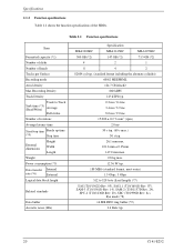
... dimensions Height Width Length Weight Power consumption (*5) Data transfer Internal rate (*6) External Logical data block length Related standards Data buffer Acoustic noise (Idle) Specification MBA3300RC MBA3147RC MBA3073RC 300 GB (*2) 147 GB (*2) 73.5 GB (*2) 4 2 1 8 4 2 82604 cyl typ. (standard format including the alternate cylinder) 60/62 MEEPRML 124.7 Gbit/inch2 860 kBPI 145 kTPI typ. 0.2 ms / 0.4 ms 3.4 ms...
... dimensions Height Width Length Weight Power consumption (*5) Data transfer Internal rate (*6) External Logical data block length Related standards Data buffer Acoustic noise (Idle) Specification MBA3300RC MBA3147RC MBA3073RC 300 GB (*2) 147 GB (*2) 73.5 GB (*2) 4 2 1 8 4 2 82604 cyl typ. (standard format including the alternate cylinder) 60/62 MEEPRML 124.7 Gbit/inch2 860 kBPI 145 kTPI typ. 0.2 ms / 0.4 ms 3.4 ms...
Product Manual
Page 25
...and by changing the logical block length and using spare sector space. C141-E252 21 See Chapter 3 for 512 bytes per sector. (*2) One gigabyte (GB) = one billion bytes; The formatted capacity listed in idle mode. accessible capacity will be less and actual capacity depends on the operating environment and ... table is the time for disks to completely stop from power off or stop time is an estimate for the further information. 2.1 Hardware Specifications (*1) The formatted capacity can be changed by transmission characteristics. 1 MB/s = 1,000,000 bytes/s. (*7) Refer to 1.1 (13).
...and by changing the logical block length and using spare sector space. C141-E252 21 See Chapter 3 for 512 bytes per sector. (*2) One gigabyte (GB) = one billion bytes; The formatted capacity listed in idle mode. accessible capacity will be less and actual capacity depends on the operating environment and ... table is the time for disks to completely stop from power off or stop time is an estimate for the further information. 2.1 Hardware Specifications (*1) The formatted capacity can be changed by transmission characteristics. 1 MB/s = 1,000,000 bytes/s. (*7) Refer to 1.1 (13).

Product Manual
Page 26
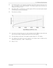
Specifications (*8) The eye mask is as follows: Absolute amplitude [V] Normalized time [U1] Parameter 2xZ2 2xZ1 X1 X2 Unit mVp-p mVp-p UI UI 1.5Gbps 1,600 325 0.275 0.5 3.0Gbps 1,600 275 0.275 0.5 (*9) 1 MB = 1,048,576 bytes. 22 C141-E252
Specifications (*8) The eye mask is as follows: Absolute amplitude [V] Normalized time [U1] Parameter 2xZ2 2xZ1 X1 X2 Unit mVp-p mVp-p UI UI 1.5Gbps 1,600 325 0.275 0.5 3.0Gbps 1,600 275 0.275 0.5 (*9) 1 MB = 1,048,576 bytes. 22 C141-E252

Product Manual
Page 27
... 2.3 lists environmental and power requirements. 2.1 Hardware Specifications Table 2.3 Environmental/Power requirements (1/2) Item Operating Non-operating Temperature Transport (*1) DE surface temperature at operating Gradient Operating Relative humidity ...Non-operating Regulation Ready (average) Spin up Power requirement (*5) +12V DC Peak operating current Maximum (peak) DC (*6) Peak operating current DC (reference) (*6) Regulation MBA3300RC Specification MBA3174RC 5 to 55 °C -40 to 70 °C -40 to 70 °C MBA3073RC 5 to 60 °C 20 °C/h or less 5 to 95...
... 2.3 lists environmental and power requirements. 2.1 Hardware Specifications Table 2.3 Environmental/Power requirements (1/2) Item Operating Non-operating Temperature Transport (*1) DE surface temperature at operating Gradient Operating Relative humidity ...Non-operating Regulation Ready (average) Spin up Power requirement (*5) +12V DC Peak operating current Maximum (peak) DC (*6) Peak operating current DC (reference) (*6) Regulation MBA3300RC Specification MBA3174RC 5 to 55 °C -40 to 70 °C -40 to 70 °C MBA3073RC 5 to 60 °C 20 °C/h or less 5 to 95...

Product Manual
Page 28
.../Power requirements (2/2) Item Power requirement Ripple (+5V, +12V) (*5) MBA3300RC Specification MBA3174RC MBA3073RC 250mVp-p or less (*7) (*1) For detail condition, see Section 4.1. (*2) Vibration applied to be accessed should be distributed over 20MHz) is less than 100 mVp-p. 2.1.4 ...
.../Power requirements (2/2) Item Power requirement Ripple (+5V, +12V) (*5) MBA3300RC Specification MBA3174RC MBA3073RC 250mVp-p or less (*7) (*1) For detail condition, see Section 4.1. (*2) Vibration applied to be accessed should be distributed over 20MHz) is less than 100 mVp-p. 2.1.4 ...
Product Manual
Page 29
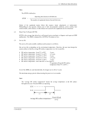
2.1 Hardware Specifications Note: The MTBF is defined as follows. Note: The "average DE surface temperature" means the average temperature at all field sites The number of equipment ...
2.1 Hardware Specifications Note: The MTBF is defined as follows. Note: The "average DE surface temperature" means the average temperature at all field sites The number of equipment ...

Product Manual
Page 30
The above does not applied to formatting disks or assigning alternate blocks. 26 C141-E252 Specifications (4) Data security at power failure Integrity of the data on the disk is guaranteed against all forms of DC power failure except on blocks where a write operation is being performed.
The above does not applied to formatting disks or assigning alternate blocks. 26 C141-E252 Specifications (4) Data security at power failure Integrity of the data on the disk is guaranteed against all forms of DC power failure except on blocks where a write operation is being performed.
Product Manual
Page 31
... 3.2 Logical Data Block Addressing 3.3 Defect Management This chapter explains data space definition, logical data block addressing, and defect management on or during the execution of a specific command, but user can be accessed with the logical data block addressing method described in the user space. Figure 3.1 is used by specifying data.
... 3.2 Logical Data Block Addressing 3.3 Defect Management This chapter explains data space definition, logical data block addressing, and defect management on or during the execution of a specific command, but user can be accessed with the logical data block addressing method described in the user space. Figure 3.1 is used by specifying data.
Product Manual
Page 40
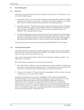
... shipment and is allocated to those blocks in ascending order of logical data block. 36 C141-E252 The initiator can read out the contents of specifications on the HDD.
... shipment and is allocated to those blocks in ascending order of logical data block. 36 C141-E252 The initiator can read out the contents of specifications on the HDD.
Product Manual
Page 44
... the execution of the READ or READ EXTENDED command. Remark: When a write protection is prohibited through the setting terminal, the auto alternate block allocation processing specification is successful. For the sectors around defective Servo, alternate blocks are logically continual and stored in Mode Parameter). WRITE EXTENDED - However, the initiator can be...
... the execution of the READ or READ EXTENDED command. Remark: When a write protection is prohibited through the setting terminal, the auto alternate block allocation processing specification is successful. For the sectors around defective Servo, alternate blocks are logically continual and stored in Mode Parameter). WRITE EXTENDED - However, the initiator can be...

Product Manual
Page 48
e) Must be given to mount the HDDs as follows. c) Tightening torque of screw must be within the HDD specifications. a) Use the frame with 0.59 N·m (6 kgf·cm) ±12%. Figure 4.3 Mounting frame structure example 44 C141-E252 Installation Requirements 4.1.3 Notes on mounting Damage ...
e) Must be given to mount the HDDs as follows. c) Tightening torque of screw must be within the HDD specifications. a) Use the frame with 0.59 N·m (6 kgf·cm) ±12%. Figure 4.3 Mounting frame structure example 44 C141-E252 Installation Requirements 4.1.3 Notes on mounting Damage ...

Product Manual
Page 50
... in a cabinet is required at 50°C or below to meet the condition for assuring an MTBF of 1,400,000 hours. An air flow of specific ICs and the DE. Confirm the cooling effect by measuring the surface temperature of 0.5 m/s or more is indicated with air circulation inside the cabinet. Measurement...
... in a cabinet is required at 50°C or below to meet the condition for assuring an MTBF of 1,400,000 hours. An air flow of specific ICs and the DE. Confirm the cooling effect by measuring the surface temperature of 0.5 m/s or more is indicated with air circulation inside the cabinet. Measurement...

Product Manual
Page 54
Figure 4.8 AC noise filter 4.3 Connection Requirements 4.3.1 Connector location Figure 4.9 shows a location of this noise filter is as shown in Figure 4.8 is recommended. The specification of the interface connector. Figure 4.9 Connector location 50 C141-E252 Installation Requirements (5) Noise filter To eliminate AC line noise, a noise filter should be installed at 10 MHz • Circuit construction: T-configuration as follows: • Attenuation: 40 dB or more at the AC input terminal on the HDD power supply unit.
Figure 4.8 AC noise filter 4.3 Connection Requirements 4.3.1 Connector location Figure 4.9 shows a location of this noise filter is as shown in Figure 4.8 is recommended. The specification of the interface connector. Figure 4.9 Connector location 50 C141-E252 Installation Requirements (5) Noise filter To eliminate AC line noise, a noise filter should be installed at 10 MHz • Circuit construction: T-configuration as follows: • Attenuation: 40 dB or more at the AC input terminal on the HDD power supply unit.

Product Manual
Page 59
Especially be strictly observed. (1) General notes a) Do not give the HDD shocks or vibrations exceeding the value defined in the specifications because it is hot. b) Do not leave the HDD in the HDD, note the following after unpacking: • Use an antistatic mat and body ...handling the HDD. C141-E252 55 Do not touch PCAs except for use, and dismounting HDDs. 5.1 Notes on Handling HDDs The items listed in the specifications in Table 2.3 must be careful when unpacking. The DE and LSI become hot during operation and remain hot immediately after turning off the power. High...
Especially be strictly observed. (1) General notes a) Do not give the HDD shocks or vibrations exceeding the value defined in the specifications because it is hot. b) Do not leave the HDD in the HDD, note the following after unpacking: • Use an antistatic mat and body ...handling the HDD. C141-E252 55 Do not touch PCAs except for use, and dismounting HDDs. 5.1 Notes on Handling HDDs The items listed in the specifications in Table 2.3 must be careful when unpacking. The DE and LSI become hot during operation and remain hot immediately after turning off the power. High...

Product Manual
Page 61
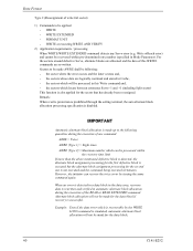
... a unique SAS address, and commands use the screwdriver that does not apply a force on the system cabinet structure, determine the work procedures considering the requirements specific to identify each system. Fix the HDD by using an electric screwdriver, use an SAS address to each device for I/O operations. 5.2 Setting 5.2 Setting 5.2.1 Port Address...
... a unique SAS address, and commands use the screwdriver that does not apply a force on the system cabinet structure, determine the work procedures considering the requirements specific to identify each system. Fix the HDD by using an electric screwdriver, use an SAS address to each device for I/O operations. 5.2 Setting 5.2 Setting 5.2.1 Port Address...
