
Product Manual
Page 4
.../996D Rev.8c [NCITS.306:1998] T10/1157D Rev.24 T10/1365D Rev.10 Title SCSI Primary Commands-2 (SPC-2) SCSI-3 Block Commands (SBC) SCSI Architecture Model-2 (SAM-2) SCSI Parallel Interface-4 (SPI-4) *1 ANSI = American National Standard Institute In case of conflict between this manual and any packaging part of China This product...
.../996D Rev.8c [NCITS.306:1998] T10/1157D Rev.24 T10/1365D Rev.10 Title SCSI Primary Commands-2 (SPC-2) SCSI-3 Block Commands (SBC) SCSI Architecture Model-2 (SAM-2) SCSI Parallel Interface-4 (SPI-4) *1 ANSI = American National Standard Institute In case of conflict between this manual and any packaging part of China This product...
Product Manual
Page 7
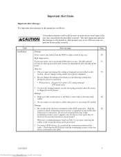
...on , the overcurrent protection fuse of the terminating resistor power supplier may be careful of the connection position of the CN2 setting terminal (NP model only) 3. Damage 1. Do not change the setting of the SCSI connectors. Do not connect or disconnect cables when power is not provided.... Check that system power is turned on .(except NC model) Damage 1. When the recommended parts listed in Table 4.2 are as follows: Task Installation A hazardous situation could result in minor or moderate ...
...on , the overcurrent protection fuse of the terminating resistor power supplier may be careful of the connection position of the CN2 setting terminal (NP model only) 3. Damage 1. Do not change the setting of the SCSI connectors. Do not connect or disconnect cables when power is not provided.... Check that system power is turned on .(except NC model) Damage 1. When the recommended parts listed in Table 4.2 are as follows: Task Installation A hazardous situation could result in minor or moderate ...
Product Manual
Page 11
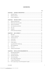
... 1 GENERAL DESCRIPTION 13 1.1 Standard Features ...14 1.2 Hardware Structure ...18 1.3 System Configuration...19 CHAPTER 2 SPECIFICATIONS 21 2.1 Hardware Specifications 21 2.1.1 Model name and order number 21 2.1.2 Function specifications...22 2.1.3 Environmental specifications 25 2.1.4 Error rate ...26 2.1.5 Reliability ...27 2.2 SCSI Function Specifications 29...50 4.1.3 Notes on mounting ...50 4.2 Power Supply Requirements 53 4.3 Connection Requirements 58 4.3.1 SCA2 connector type 16-bit SCSI model (NC model 58 C141-E270 7 Downloaded from www.Manualslib.com manuals search engine
... 1 GENERAL DESCRIPTION 13 1.1 Standard Features ...14 1.2 Hardware Structure ...18 1.3 System Configuration...19 CHAPTER 2 SPECIFICATIONS 21 2.1 Hardware Specifications 21 2.1.1 Model name and order number 21 2.1.2 Function specifications...22 2.1.3 Environmental specifications 25 2.1.4 Error rate ...26 2.1.5 Reliability ...27 2.2 SCSI Function Specifications 29...50 4.1.3 Notes on mounting ...50 4.2 Power Supply Requirements 53 4.3 Connection Requirements 58 4.3.1 SCA2 connector type 16-bit SCSI model (NC model 58 C141-E270 7 Downloaded from www.Manualslib.com manuals search engine
Product Manual
Page 12
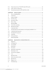
4.3.2 4.3.3 4.3.4 68-pin connector type 16-bit SCSI model (NP model 60 Cable connector requirements 67 External operator panel (on NP model drives only 68 CHAPTER 5 INSTALLATION 71 5.1 Notes on Handling HDDs 71 5.2 Connections...73 5.3 Setting Terminals ...75 5.3.1 SCSI ID setting...76 5.3.2 Each mode setting ...78 5.3.3 Mode settings ...80 5.4 Mounting HDDs...81 5.4.1 Check before mounting ...81 5.4.2 Mounting...
4.3.2 4.3.3 4.3.4 68-pin connector type 16-bit SCSI model (NP model 60 Cable connector requirements 67 External operator panel (on NP model drives only 68 CHAPTER 5 INSTALLATION 71 5.1 Notes on Handling HDDs 71 5.2 Connections...73 5.3 Setting Terminals ...75 5.3.1 SCSI ID setting...76 5.3.2 Each mode setting ...78 5.3.3 Mode settings ...80 5.4 Mounting HDDs...81 5.4.1 Check before mounting ...81 5.4.2 Mounting...
Product Manual
Page 13
...), (B-44-xx), (B-47-xx), (B-48-00), (B-49-00), (B-4D-xx) and (B-4E-00): SCSI interface error 116 APPENDIX A SETTING TERMINALS 117 A.1 Setting Terminals (on NP model only 118 APPENDIX B CONNECTOR SIGNAL ALLOCATION 119 B.1 SCSI Connector Signal Allocation: SCA2 type LVD 16-bit SCSI 120 B.2 SCSI Connector Signal Allocation: 68-pin type...
...), (B-44-xx), (B-47-xx), (B-48-00), (B-49-00), (B-4D-xx) and (B-4E-00): SCSI interface error 116 APPENDIX A SETTING TERMINALS 117 A.1 Setting Terminals (on NP model only 118 APPENDIX B CONNECTOR SIGNAL ALLOCATION 119 B.1 SCSI Connector Signal Allocation: SCA2 type LVD 16-bit SCSI 120 B.2 SCSI Connector Signal Allocation: 68-pin type...

Product Manual
Page 14
... Figure 4.12 Figure 4.13 Figure 4.14 Figure 4.15 Figure 4.16 Figure 4.17 Figure 4.18 Figure 4.19 Figure 4.20 Figure 4.21 Figure 4.22 NC model dimensions...48 NP model dimensions ...49 HDD orientations...50 Mounting frame structure ...51 Limitation of side-mounting 52 Surface temperature measurement points 53 Current waveform (Spin-up 54...
... Figure 4.12 Figure 4.13 Figure 4.14 Figure 4.15 Figure 4.16 Figure 4.17 Figure 4.18 Figure 4.19 Figure 4.20 Figure 4.21 Figure 4.22 NC model dimensions...48 NP model dimensions ...49 HDD orientations...50 Mounting frame structure ...51 Limitation of side-mounting 52 Surface temperature measurement points 53 Current waveform (Spin-up 54...
Product Manual
Page 15
Figure 4.23 External operator panel circuit example 68 Figure 5.1 Figure 5.2 Figure 5.3 Figure 5.4 Figure 5.5 SCSI bus connections ...74 Setting terminals location (on NP models only 75 CN2 setting terminal (on NP models only 76 Checking the SCSI connection (A 85 Checking the SCSI connection (B 86 Figure 6.1 Figure 6.2 Figure 6.3 Figure 6.4 Test flowchart ...103 Single HDD packaging...108 Multi-box packaging...110 Fraction packaging ...111 Figure 7.1 Sense data format...114 C141-E270 11 Downloaded from www.Manualslib.com manuals search engine
Figure 4.23 External operator panel circuit example 68 Figure 5.1 Figure 5.2 Figure 5.3 Figure 5.4 Figure 5.5 SCSI bus connections ...74 Setting terminals location (on NP models only 75 CN2 setting terminal (on NP models only 76 Checking the SCSI connection (A 85 Checking the SCSI connection (B 86 Figure 6.1 Figure 6.2 Figure 6.3 Figure 6.4 Test flowchart ...103 Single HDD packaging...108 Multi-box packaging...110 Fraction packaging ...111 Figure 7.1 Sense data format...114 C141-E270 11 Downloaded from www.Manualslib.com manuals search engine
Product Manual
Page 16
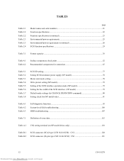
......77 Setting SCSI terminator power supply (NP model 78 Motor start mode setting...78 Write protect setting (NP model 79 Setting of the SCSI interface operation mode (NP model 79 Setting the bus width of the SCSI interface (NP model 79 Default mode settings (by CHANGE DEFINITION ... functions ...95 System-level field troubleshooting 106 HDD troubleshooting ...107 Table 7.1 Definition of sense data ...115 Table A.1 CN2 setting terminal (on NP model drives only 118 Table B.1 Table B.2 SCSI connector (SCA2 type LVD 16-bit SCSI): CN1 120 SCSI connector (68-pin type LVD 16-bit SCSI...
......77 Setting SCSI terminator power supply (NP model 78 Motor start mode setting...78 Write protect setting (NP model 79 Setting of the SCSI interface operation mode (NP model 79 Setting the bus width of the SCSI interface (NP model 79 Default mode settings (by CHANGE DEFINITION ... functions ...95 System-level field troubleshooting 106 HDD troubleshooting ...107 Table 7.1 Definition of sense data ...115 Table A.1 CN2 setting terminal (on NP model drives only 118 Table B.1 Table B.2 SCSI connector (SCA2 type LVD 16-bit SCSI): CN1 120 SCSI connector (68-pin type LVD 16-bit SCSI...

Product Manual
Page 18
... SCSI devices on the same SCSI bus is extremely compact. See subsection 5.3.2 for SCSI-2. 8-bit data bus is available only with NP model. 1.1 Standard Features (1) Compactness Since the SCSI controller circuit is embedded in electrical and electronic equipment (RoHS) directive issued by European Union ...of the use of certain Hazardous Substances in the standard 3.5-inch hard disk drive form factor, the HDD is varied as follows. • 8-bit SCSI: 8 drives max. (option for NP model) • 16-bit SCSI: 16 drives max. 14 Downloaded from www.Manualslib.com manuals search engine C141...
... SCSI devices on the same SCSI bus is extremely compact. See subsection 5.3.2 for SCSI-2. 8-bit data bus is available only with NP model. 1.1 Standard Features (1) Compactness Since the SCSI controller circuit is embedded in electrical and electronic equipment (RoHS) directive issued by European Union ...of the use of certain Hazardous Substances in the standard 3.5-inch hard disk drive form factor, the HDD is varied as follows. • 8-bit SCSI: 8 drives max. (option for NP model) • 16-bit SCSI: 16 drives max. 14 Downloaded from www.Manualslib.com manuals search engine C141...
Product Manual
Page 24
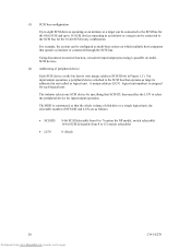
... on multiSCSI devices. (2) Addressing of SCSI ID and LUN are as follows: • SCSI ID: • LUN: 8-bit SCSI:Selectable from 0 to 7 (option for NP model, switch selectable) 16-bit SCSI:Selectable from 0 to 15 (switch selectable) 0 (fixed) 20 Downloaded from www.Manualslib.com manuals search engine C141-E270 For input.../output operation, a peripheral device attached to select the peripheral device for each logical unit. The HDD is constructed so that the whole volume of disk drive is assigned for input/output operation.
... on multiSCSI devices. (2) Addressing of SCSI ID and LUN are as follows: • SCSI ID: • LUN: 8-bit SCSI:Selectable from 0 to 7 (option for NP model, switch selectable) 16-bit SCSI:Selectable from 0 to 15 (switch selectable) 0 (fixed) 20 Downloaded from www.Manualslib.com manuals search engine C141-E270 For input.../output operation, a peripheral device attached to select the peripheral device for each logical unit. The HDD is constructed so that the whole volume of disk drive is assigned for input/output operation.

Product Manual
Page 25
...specifications of the HDD and the functional specifications of the SCSI. 2.1 Hardware Specifications 2.1.1 Model name and order number Each model has a different recording capacities and interface connector type when shipped. C141-E270 21 ...Model names and order numbers Model name Order number SCSI type MBA3300NC MBA3300NP MBA3147NC MBA3147NP MBA3073NC MBA3073NP CA06708-B400 CA06708-B850 CA06708-B200 CA06708-B650 CA06708-B100 CA06708-B550 SCA2, LVD 68-pin, LVD SCA2, LVD 68-pin, LVD SCA2, LVD 68-pin, LVD Capacity (user area) 300 GB (*) 147 GB (*) 73.5 GB (*) (*) One gigabyte (GB...
...specifications of the HDD and the functional specifications of the SCSI. 2.1 Hardware Specifications 2.1.1 Model name and order number Each model has a different recording capacities and interface connector type when shipped. C141-E270 21 ...Model names and order numbers Model name Order number SCSI type MBA3300NC MBA3300NP MBA3147NC MBA3147NP MBA3073NC MBA3073NP CA06708-B400 CA06708-B850 CA06708-B200 CA06708-B650 CA06708-B100 CA06708-B550 SCA2, LVD 68-pin, LVD SCA2, LVD 68-pin, LVD SCA2, LVD 68-pin, LVD Capacity (user area) 300 GB (*) 147 GB (*) 73.5 GB (*) (*) One gigabyte (GB...
Product Manual
Page 33
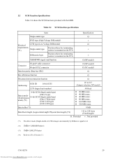
... (Single-ended or LVD) changes automatically by Diffsence signal level. (*2) 1MB/s=1,000,000 bytes/s (*3) 1MB=1,048,576 bytes (*4) Refer to #15 (Jumper selection, NP model) #0 fixed Ο 20 MB/s max. Ο 40 MB/s max. Ο 40 MB/s max. Ο 80 MB/s max. Ο 160 MB/s...where the terminating resistor is mounted on the PCA × TERMPWR signal send function Ο (NP model) Connector 68-pin P cable connector 80-pin SCA2 connector Ο (NP model) Ο (NC model) Data bus parity (Data bus CRC) Ο Bus arbitration function Ο Disconnection/reconnection function ...
... (Single-ended or LVD) changes automatically by Diffsence signal level. (*2) 1MB/s=1,000,000 bytes/s (*3) 1MB=1,048,576 bytes (*4) Refer to #15 (Jumper selection, NP model) #0 fixed Ο 20 MB/s max. Ο 40 MB/s max. Ο 40 MB/s max. Ο 80 MB/s max. Ο 160 MB/s...where the terminating resistor is mounted on the PCA × TERMPWR signal send function Ο (NP model) Connector 68-pin P cable connector 80-pin SCA2 connector Ο (NP model) Ο (NC model) Data bus parity (Data bus CRC) Ο Bus arbitration function Ο Disconnection/reconnection function ...
Product Manual
Page 42
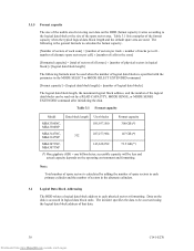
... the disk is accessed in logical data block units. Table 3.1 Format capacity Model Data block length User blocks Format capacity MBA3300NC, MBA3300NP 585,937,500 300 GB (*) MBA3147NC, MBA3147NP 512 287,277,984 147 GB (*) MBA3073NC, MBA3073NP 143,638,992 73.5 GB (*) (*) One gigabyte (GB) = one billion bytes; The initiator specifies the data to be less and...
... the disk is accessed in logical data block units. Table 3.1 Format capacity Model Data block length User blocks Format capacity MBA3300NC, MBA3300NP 585,937,500 300 GB (*) MBA3147NC, MBA3147NP 512 287,277,984 147 GB (*) MBA3073NC, MBA3073NP 143,638,992 73.5 GB (*) (*) One gigabyte (GB) = one billion bytes; The initiator specifies the data to be less and...

Product Manual
Page 52
The value marked with (*) indicates the dimension between mounting holes on the bottom face. [Unit: mm] Figure 4.1 NC model dimensions 48 Downloaded from www.Manualslib.com manuals search engine C141-E270
The value marked with (*) indicates the dimension between mounting holes on the bottom face. [Unit: mm] Figure 4.1 NC model dimensions 48 Downloaded from www.Manualslib.com manuals search engine C141-E270

Product Manual
Page 53
The value marked with (*) indicates the dimension between mounting holes on the bottom face. [Unit: mm] Figure 4.2 NP model dimensions C141-E270 49 Downloaded from www.Manualslib.com manuals search engine
The value marked with (*) indicates the dimension between mounting holes on the bottom face. [Unit: mm] Figure 4.2 NP model dimensions C141-E270 49 Downloaded from www.Manualslib.com manuals search engine
Product Manual
Page 61
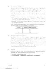
... HDD must be started sequentially using of the following procedures to Section 1.4 "Electrical Requirements" of the power supply unit. For the NP model drives, the spindle motors should be started by setting CN1-38 pin to open and CN1-78 pin to the terminating resistor is recommended. For... the NC model drives, the spindle motors should be started after a delay of 12 seconds times [SCSI ID] by the following procedures. Regarding how to Subsection 3.1....
... HDD must be started sequentially using of the following procedures to Section 1.4 "Electrical Requirements" of the power supply unit. For the NP model drives, the spindle motors should be started by setting CN1-38 pin to open and CN1-78 pin to the terminating resistor is recommended. For... the NC model drives, the spindle motors should be started after a delay of 12 seconds times [SCSI ID] by the following procedures. Regarding how to Subsection 3.1....

Product Manual
Page 62
Figure 4.12 AC noise filter (recommended) 4.3 Connection Requirements 4.3.1 SCA2 connector type 16-bit SCSI model (NC model) (1) Connectors Figure 4.13 shows the locations of connectors on the SCA2 connector type 16-bit SCSI model (NC model). SCSI connector (CN1) (including power supply) Figure 4.13 NC connectors location 58 Downloaded from www.Manualslib.com manuals search engine C141-E270
Figure 4.12 AC noise filter (recommended) 4.3 Connection Requirements 4.3.1 SCA2 connector type 16-bit SCSI model (NC model) (1) Connectors Figure 4.13 shows the locations of connectors on the SCA2 connector type 16-bit SCSI model (NC model). SCSI connector (CN1) (including power supply) Figure 4.13 NC connectors location 58 Downloaded from www.Manualslib.com manuals search engine C141-E270

Product Manual
Page 63
... shows the SCSI connector. C141-E270 59 Downloaded from www.Manualslib.com manuals search engine (2) SCSI connector and power supply connector The connector for NC model drives. See Section B.1 in the SCSI connector. The power connector is an unshielded SCA-2 connector conforming to Sections 1.3 "Physical Requirements" and Section 1.4 "Electrical Requirements" of the...
... shows the SCSI connector. C141-E270 59 Downloaded from www.Manualslib.com manuals search engine (2) SCSI connector and power supply connector The connector for NC model drives. See Section B.1 in the SCSI connector. The power connector is an unshielded SCA-2 connector conforming to Sections 1.3 "Physical Requirements" and Section 1.4 "Electrical Requirements" of the...

Product Manual
Page 64
... which has two 34-pin rows spaced 1.27 mm (0.05 inch) apart. For details on the SCSI connector. 4.3.2 68-pin connector type 16-bit SCSI model (NP model) (1) Connectors Figures 4.15 show the locations of connectors and terminals on the 68-pin connector type 16-bit SCSI... model (NP model). • Power supply connector • SCSI connector • External operator panel connector External operator panel connector (CN2) Power supply connector (CN1) External operator panel connector (...
... which has two 34-pin rows spaced 1.27 mm (0.05 inch) apart. For details on the SCSI connector. 4.3.2 68-pin connector type 16-bit SCSI model (NP model) (1) Connectors Figures 4.15 show the locations of connectors and terminals on the 68-pin connector type 16-bit SCSI... model (NP model). • Power supply connector • SCSI connector • External operator panel connector External operator panel connector (CN2) Power supply connector (CN1) External operator panel connector (...

Product Manual
Page 71
Table 4.2 Recommended components for connection Applicable model Type Name NC SCSI connector (CN1) Connector Part number (Size) 787311-4 71743-1085 Manufacturer Tyco Electronics AMP Reference (*1) Molex Cable socket DHJ... ELECTRIC External operator panel (CN1) Contact A3B-2630SCC HIROSE ELECTRIC S3 Cable (AWG26 to 36) Cable socket housing FCN-723J024/2M FUJITSU TAKAMIZAWA External operator panel (CN2) Contact FCN-723J-G/AM FUJITSU TAKAMIZAWA S4 Cable (AWG28) (*1) See Figure 4.22. (1) SCSI cable Refer to Section 1.3 "Physical Requirements" and Section 1.4 "...
Table 4.2 Recommended components for connection Applicable model Type Name NC SCSI connector (CN1) Connector Part number (Size) 787311-4 71743-1085 Manufacturer Tyco Electronics AMP Reference (*1) Molex Cable socket DHJ... ELECTRIC External operator panel (CN1) Contact A3B-2630SCC HIROSE ELECTRIC S3 Cable (AWG26 to 36) Cable socket housing FCN-723J024/2M FUJITSU TAKAMIZAWA External operator panel (CN2) Contact FCN-723J-G/AM FUJITSU TAKAMIZAWA S4 Cable (AWG28) (*1) See Figure 4.22. (1) SCSI cable Refer to Section 1.3 "Physical Requirements" and Section 1.4 "...

