Specifications
Page 17
... to Link Specification Commands 1-10 Types of Command and Disconnect Processing 1-12 Sense data in not ready state...1-25 Outline of SCSI Bus Error Recovery Processing 1-27 Outline of disk drive error recovery processing 1-27 Reset processing during write...1-29 Table 3.1 Table 3.2 Table 3.3 Table 3.4 Table 3.5 Table 3.6 MODE SENSE Data ...Table 5.3 Table 5.4 Table 5.5 Sense key...5-5 Additional sense code and additional sense code qualifier 5-6 Sense data error classification ...5-15 Error recovery processing procedures 5-18 Disk drive errors and number of retries 5-27 C141-C010 xiii
... to Link Specification Commands 1-10 Types of Command and Disconnect Processing 1-12 Sense data in not ready state...1-25 Outline of SCSI Bus Error Recovery Processing 1-27 Outline of disk drive error recovery processing 1-27 Reset processing during write...1-29 Table 3.1 Table 3.2 Table 3.3 Table 3.4 Table 3.5 Table 3.6 MODE SENSE Data ...Table 5.3 Table 5.4 Table 5.5 Sense key...5-5 Additional sense code and additional sense code qualifier 5-6 Sense data error classification ...5-15 Error recovery processing procedures 5-18 Disk drive errors and number of retries 5-27 C141-C010 xiii

Specifications
Page 19
In a number of each individual command in the COMMAND phase. Bit Byte 7 0 1 2 3 4 5 6 LUN 5 4 3 2 1 0 Operation Code Logical Block Address (MSB) Logical Block Address Logical Block Address (LSB) Transfer .... In the explanations in Figures 1.1, 1.2 and 1.3. The CDB used by the CDB (Command Descriptor Block). The CDB is mentioned as the target (TARG) on the SCSI bus.
In a number of each individual command in the COMMAND phase. Bit Byte 7 0 1 2 3 4 5 6 LUN 5 4 3 2 1 0 Operation Code Logical Block Address (MSB) Logical Block Address Logical Block Address (LSB) Transfer .... In the explanations in Figures 1.1, 1.2 and 1.3. The CDB used by the CDB (Command Descriptor Block). The CDB is mentioned as the target (TARG) on the SCSI bus.

Specifications
Page 21
... shown below are described in Section 1.7.3) b. a. Command code Command code specifies the type of command in each group. (2) LUN (Logical Unit Number) This field specifies the address of the logical unit (device) connected under the TARG in cases where the IDENTIFY message is not used , the... that a zero be specified in this field may be executed. The groups of the data block on the disk media to be changed in future SCSI standards. 1.1 Command Format (1) Operation code Bit 7 6 5 4 3 2 1 0 Group Code Command Code The leading byte of all CDBs shows the format and ...
... shown below are described in Section 1.7.3) b. a. Command code Command code specifies the type of command in each group. (2) LUN (Logical Unit Number) This field specifies the address of the logical unit (device) connected under the TARG in cases where the IDENTIFY message is not used , the... that a zero be specified in this field may be executed. The groups of the data block on the disk media to be changed in future SCSI standards. 1.1 Command Format (1) Operation code Bit 7 6 5 4 3 2 1 0 Group Code Command Code The leading byte of all CDBs shows the format and ...

Specifications
Page 22
...transfer data length field. It is possible to specify a block count ranging from 0 to the INIT. 1-4 C141-C010 The IDD transfers either the number of effective bytes of the type of information specified in the command, or the value specified in the "Transfer Byte Length" field, whichever is ... 3. Transfer byte length or parameter list length When this field is executed. In commands which the INIT is specified by the number of logical data blocks or the number of bytes. There are described in the individual command specifications in length, if the field's specified value is 0, it is...
...transfer data length field. It is possible to specify a block count ranging from 0 to the INIT. 1-4 C141-C010 The IDD transfers either the number of effective bytes of the type of information specified in the command, or the value specified in the "Transfer Byte Length" field, whichever is ... 3. Transfer byte length or parameter list length When this field is executed. In commands which the INIT is specified by the number of logical data blocks or the number of bytes. There are described in the individual command specifications in length, if the field's specified value is 0, it is...

Specifications
Page 27
...and status pointers are terminated. C141-C010 1-9 After that commands with a Link specification are updated to the initial values for which data transfer on the SCSI bus is necessary, the DATA IN or the DATA OUT phase is executed. 6) When execution of the command is completed, the TARG reports the execution... of the TARG and specification of the LUN by the group code in the first byte of the CDB and requests transfer of the necessary number of bytes. 5) The TARG investigates the contents of the IDD when commands with link specifications are the same as in the case of single command...
...and status pointers are terminated. C141-C010 1-9 After that commands with a Link specification are updated to the initial values for which data transfer on the SCSI bus is necessary, the DATA IN or the DATA OUT phase is executed. 6) When execution of the command is completed, the TARG reports the execution... of the TARG and specification of the LUN by the group code in the first byte of the CDB and requests transfer of the necessary number of bytes. 5) The TARG investigates the contents of the IDD when commands with link specifications are the same as in the case of single command...

Specifications
Page 30
... command queuing, in a command's execution process (after the COMMAND phase is completed, or during or after the completion of Command and Disconnect Processing Commands with a number of processing modes, other than cases where the command is in the execution sequence. Command Processing Table 1.2 Types of data transfer), disconnect processing is performed...
... command queuing, in a command's execution process (after the COMMAND phase is completed, or during or after the completion of Command and Disconnect Processing Commands with a number of processing modes, other than cases where the command is in the execution sequence. Command Processing Table 1.2 Types of data transfer), disconnect processing is performed...

Specifications
Page 32
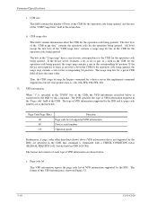
...MESSAGE REJECT message, the IDD executes the command with the INIT after waiting 200 ms or longer, the IDD executes the predetermined number of the command is complete and there is actually no necessity for reconnection processing and generates sense data indicating ABORTED COMMAND[=B]/Select /...timeout processing, then enters the BUS FREE phase. However, by issuing the SAVE DATA POINTER message, processing time increases due to the SCSI bus remaining as is as a result of the pointer restore operation that was being executed during reconnection processing for the status report, the...
...MESSAGE REJECT message, the IDD executes the command with the INIT after waiting 200 ms or longer, the IDD executes the predetermined number of the command is complete and there is actually no necessity for reconnection processing and generates sense data indicating ABORTED COMMAND[=B]/Select /...timeout processing, then enters the BUS FREE phase. However, by issuing the SAVE DATA POINTER message, processing time increases due to the SCSI bus remaining as is as a result of the pointer restore operation that was being executed during reconnection processing for the status report, the...

Specifications
Page 36
... be issued together with a HEAD OF QUEUE message. 1-18 C141-C010 If the HEAD OF QUEUE message is full, it responds to the IDD. The number of a tagged command, the IDD responds with a BUSY status. All commands received with a SIMPLE message before commands are received with an ORDERED message are received...
... be issued together with a HEAD OF QUEUE message. 1-18 C141-C010 If the HEAD OF QUEUE message is full, it responds to the IDD. The number of a tagged command, the IDD responds with a BUSY status. All commands received with a SIMPLE message before commands are received with an ORDERED message are received...

Specifications
Page 37
...unit. 1.5.1 Generation of the UNIT ATTENTION condition Events which had their commands cleared (excluding the INIT that have already been completed. See "SCSI Physical Interface Specifications" for all the INITs which cause a UNIT ATTENTION condition to clear some or all the commands in the queue is the...following . If "01" is released, it is released. The additional sense code Commands cleared by the IDD when tagged commands are one of a number of sense hold states, and when this sense hold state is released, the queue is received by another INIT [=2F-00] is a function ...
...unit. 1.5.1 Generation of the UNIT ATTENTION condition Events which had their commands cleared (excluding the INIT that have already been completed. See "SCSI Physical Interface Specifications" for all the INITs which cause a UNIT ATTENTION condition to clear some or all the commands in the queue is the...following . If "01" is released, it is released. The additional sense code Commands cleared by the IDD when tagged commands are one of a number of sense hold states, and when this sense hold state is released, the queue is received by another INIT [=2F-00] is a function ...

Specifications
Page 42
...the CHECK CONDITION status and terminates both the first command and the second command abnormally. 1.7.2 Illegal LUN specification The logical unit number (LUN) supported by Fujitsu. Furthermore, the not ready state is defined as MODE SELECT parameters and disk media defect information is read from the system...] (nn: tag No.). At this operation is completed, the IDD is in either of the following operations, depending on the disk drive and each type of system information is illegal. However, the sense data transferred to the INIT for that command indicates that the LUN ...
...the CHECK CONDITION status and terminates both the first command and the second command abnormally. 1.7.2 Illegal LUN specification The logical unit number (LUN) supported by Fujitsu. Furthermore, the not ready state is defined as MODE SELECT parameters and disk media defect information is read from the system...] (nn: tag No.). At this operation is completed, the IDD is in either of the following operations, depending on the disk drive and each type of system information is illegal. However, the sense data transferred to the INIT for that command indicates that the LUN ...

Specifications
Page 48
... state is reported continuously for input/output operation requests, it is allocated in defect sector units for defective sectors on the disk drive. Alternate cylinders for all the logical data blocks in the "Product Manual." Alternate data blocks are the same and it cannot ... management techniques and alternate block allocation techniques, Chapter 3 "Data Format" in the user space as if they were error free. The number of defect management techniques, see Figure 1.5). The IDD manages defects for each cell as alternate sectors for defective sectors is necessary for error...
... state is reported continuously for input/output operation requests, it is allocated in defect sector units for defective sectors on the disk drive. Alternate cylinders for all the logical data blocks in the "Product Manual." Alternate data blocks are the same and it cannot ... management techniques and alternate block allocation techniques, Chapter 3 "Data Format" in the user space as if they were error free. The number of defect management techniques, see Figure 1.5). The IDD manages defects for each cell as alternate sectors for defective sectors is necessary for error...

Specifications
Page 50
...the sectors in each track according to 1) in the ascending order of cylinder numbers. 3) Within the next head of the same cell, succeeding logical data blocks are allocated to the sectors in each drive. Also, data blocks in the user space. Command Processing 1.8.2 Logical block ...addressing The IDD uses logical data block addressing which specifies 2 continuous binary numbers for the user to access the alternate area. Furthermore, the...
...the sectors in each track according to 1) in the ascending order of cylinder numbers. 3) Within the next head of the same cell, succeeding logical data blocks are allocated to the sectors in each drive. Also, data blocks in the user space. Command Processing 1.8.2 Logical block ...addressing The IDD uses logical data block addressing which specifies 2 continuous binary numbers for the user to access the alternate area. Furthermore, the...

Specifications
Page 52
..., data transfer and disconnection (the operations in 3) and 4) above) are repeated until all the data blocks specified in the command have been transferred. 5) If the number of blocks specified in the command to be transferred is larger than the capacity of a cache segment and if the data transfer rate of the... INIT is lower than the data transfer rate of the disk drive, the empty space in the data buffer disappears from step 3) and the IDD may soon not be able to the SCSI bus with the timing specified in the MODE SELECT parameter (see Section 2.1.2) to the data...
..., data transfer and disconnection (the operations in 3) and 4) above) are repeated until all the data blocks specified in the command have been transferred. 5) If the number of blocks specified in the command to be transferred is larger than the capacity of a cache segment and if the data transfer rate of the... INIT is lower than the data transfer rate of the disk drive, the empty space in the data buffer disappears from step 3) and the IDD may soon not be able to the SCSI bus with the timing specified in the MODE SELECT parameter (see Section 2.1.2) to the data...

Specifications
Page 56
Therefore, if the total number of bytes of data specified in the command is requested by IDD. 2.2 Look-Ahead Cache Feature In order to use the data buffer more effectively and improve the disk drive's effective access speed, the IDD is an effective, simple cache function for the ...empty space in the data buffer reaches the amount specified in this parameter, the IDD executes reconnection processing at the point when the number of this Look-Ahead cache feature by multiple commands, mechanical access operations can prohibit the operation of data blocks remaining in this parameter,...
Therefore, if the total number of bytes of data specified in the command is requested by IDD. 2.2 Look-Ahead Cache Feature In order to use the data buffer more effectively and improve the disk drive's effective access speed, the IDD is an effective, simple cache function for the ...empty space in the data buffer reaches the amount specified in this parameter, the IDD executes reconnection processing at the point when the number of this Look-Ahead cache feature by multiple commands, mechanical access operations can prohibit the operation of data blocks remaining in this parameter,...

Specifications
Page 64
... in cases where the UNIT ATTENTION condition is held, and the UNIT ATTENTION condition is specified. This command is also executed normally when the disk drive is not in the IDD's error recovery processing (Retry), but the mode which reports "RECOVERED ERROR" is specified. If bytes 1, the "EVPD (enable ... • An error detected during command execution was recovered in the ready state or even when an illegal logical unit number (LUN) is not cleared. In the case of the SCSI-1/CCS mode, zero must be set in these bits and in this command is executed immediately without queuing in a system...
... in cases where the UNIT ATTENTION condition is held, and the UNIT ATTENTION condition is specified. This command is also executed normally when the disk drive is not in the IDD's error recovery processing (Retry), but the mode which reports "RECOVERED ERROR" is specified. If bytes 1, the "EVPD (enable ... • An error detected during command execution was recovered in the ready state or even when an illegal logical unit number (LUN) is not cleared. In the case of the SCSI-1/CCS mode, zero must be set in these bits and in this command is executed immediately without queuing in a system...

Specifications
Page 65
... (CDB byte 0) of commands generated command supported data. (4) Transfer Byte Length Byte 4 of the CDB, the "Transfer Byte Length" field, shows the number of bytes of standard INQUIRY data or VPD information that the IDD transfers the kind of the VPD information. 3.1 Control/Sense Commands (1) EVPD (Enable Vital... in this bit is one , this field specifies that the application client can receive by this bit is holding, whichever has the smallest number of the standard INQUIRY data transferred to the INIT by this bit is zero, the IDD transfers the standard INQUIRY data or the command...
... (CDB byte 0) of commands generated command supported data. (4) Transfer Byte Length Byte 4 of the CDB, the "Transfer Byte Length" field, shows the number of bytes of standard INQUIRY data or VPD information that the IDD transfers the kind of the VPD information. 3.1 Control/Sense Commands (1) EVPD (Enable Vital... in this bit is one , this field specifies that the application client can receive by this bit is holding, whichever has the smallest number of the standard INQUIRY data transferred to the INIT by this bit is zero, the IDD transfers the standard INQUIRY data or the command...

Specifications
Page 69
...bus [0/1] - 3.1 Control/Sense Commands • SCSI-2 mode [Byte 3] - TrmIOP (Terminate I/O process): TERMINATE I/O PROCESS message [0] [Byte 6] - Addr32 (Wide SCSI address 32): 32 bit SCSI addressing [0] - Vendor ID field This field ...indicates the name of the product's supplier in the synchronous mode [1] - Product ID field The product's model name is displayed in left -justified ASCII code, and always indicates FUJITSU. Product Revision field The IDD's microcode version number...
...bus [0/1] - 3.1 Control/Sense Commands • SCSI-2 mode [Byte 3] - TrmIOP (Terminate I/O process): TERMINATE I/O PROCESS message [0] [Byte 6] - Addr32 (Wide SCSI address 32): 32 bit SCSI addressing [0] - Vendor ID field This field ...indicates the name of the product's supplier in the synchronous mode [1] - Product ID field The product's model name is displayed in left -justified ASCII code, and always indicates FUJITSU. Product Revision field The IDD's microcode version number...

Specifications
Page 70
...Descriptor field This field is as shown below . A value of zero indicates that the device server supports the quick arbitrate feature. Device Serial Number field The value following byte 4 of one indicates that the device server does not support the quick arbitrate feature. n. BYTE 58 to ...of zero indicates that the device server supports information units. QAS (Quick Arbitrate Supported) bit This bit of the device serial number in the VPD information is indicated in this field. o. Command Specifications k. Clocking field This field indicates the code which do not contain ...
...Descriptor field This field is as shown below . A value of zero indicates that the device server supports the quick arbitrate feature. Device Serial Number field The value following byte 4 of one indicates that the device server does not support the quick arbitrate feature. n. BYTE 58 to ...of zero indicates that the device server supports information units. QAS (Quick Arbitrate Supported) bit This bit of the device serial number in the VPD information is indicated in this field. o. Command Specifications k. Clocking field This field indicates the code which do not contain ...
Specifications
Page 72
... a one correspondence to the INIT by the IDD) are as all have a one-for the operation code being queried. Page Code Page (Hex) 00 80 C0 Function Page code list of the CDB. The format of a field in the CDB for the operation code being queried. Command Specifications c. d. The ... for Inquiry command for a device server that command is specified in the "EVPD" bits of VPD information supported by the IDD and its page code number are specified in the CDB, that implements command support data but not vital product data is: 12h, 02h, FFh, 00h, FFh, 01h. (7) VPD ...
... a one correspondence to the INIT by the IDD) are as all have a one-for the operation code being queried. Page Code Page (Hex) 00 80 C0 Function Page code list of the CDB. The format of a field in the CDB for the operation code being queried. Command Specifications c. d. The ... for Inquiry command for a device server that command is specified in the "EVPD" bits of VPD information supported by the IDD and its page code number are specified in the CDB, that implements command support data but not vital product data is: 12h, 02h, FFh, 00h, FFh, 01h. (7) VPD ...

Specifications
Page 73
... (byte length) after byte 4. Device serial No. The format of this VPD information itself. This VPD information reports the device serial number of this VPD information and is shown in the CDB, but indicates the length of this VPD information is always X '03' ... 7 6 5 4 3 2 1 0 0 Qualifier Device Type Code 1 X'00' (Page Code) 2 X'00' 3 X'03' (Page Length) 4 X'00' (Page Code List) 5 X'80' (Device Serial No.) 6 X'C0' (Operation Mode) Figure 3.3 VPD information: VPD identifier list The values indicated in the "Qualifier" and "Device Type Code" fields in byte...
... (byte length) after byte 4. Device serial No. The format of this VPD information itself. This VPD information reports the device serial number of this VPD information and is shown in the CDB, but indicates the length of this VPD information is always X '03' ... 7 6 5 4 3 2 1 0 0 Qualifier Device Type Code 1 X'00' (Page Code) 2 X'00' 3 X'03' (Page Length) 4 X'00' (Page Code List) 5 X'80' (Device Serial No.) 6 X'C0' (Operation Mode) Figure 3.3 VPD information: VPD identifier list The values indicated in the "Qualifier" and "Device Type Code" fields in byte...