
Manual/User Guide
Page 4
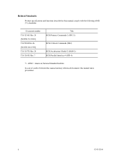
Document number T10/1236D Rev.20 [NCITS.351:2001] T10/996D Rev.8c [NCITS.306:1998] T10/1157D Rev.20 T10/1365D Rev.7 Title SCSI Primary Commands-2 (SPC-2) SCSI-3 Block Commands (SBC) SCSI Architecture Model-2 (SAM-2) SCSI Parallel Interface-4 (SPI-4) *1 ANSI = American National Standard Institute In case of conflict between this manual and any referenced document, this manual comply with the following ANSI (*1) standards. ii C141-E166 Related Standards Product specifications and functions described in this manual takes precedence.
Document number T10/1236D Rev.20 [NCITS.351:2001] T10/996D Rev.8c [NCITS.306:1998] T10/1157D Rev.20 T10/1365D Rev.7 Title SCSI Primary Commands-2 (SPC-2) SCSI-3 Block Commands (SBC) SCSI Architecture Model-2 (SAM-2) SCSI Parallel Interface-4 (SPI-4) *1 ANSI = American National Standard Institute In case of conflict between this manual and any referenced document, this manual comply with the following ANSI (*1) standards. ii C141-E166 Related Standards Product specifications and functions described in this manual takes precedence.
Manual/User Guide
Page 5
...INSTALLATION REQUIREMENTS This chapter describes the basic physical and electrical requirements for setting device number and operation modes, mounting the disk drive, connecting the cables, and confirming drive operation. The need arises, use in details how collect the information for operation ... describes the MAP3147NC/NP, MAP3735NC/NP and MAP3367NC/NP (hereafter, MAP series), 3.5 type fixed disk drives with an embedded SCSI controller. Chapter 2 SPECIFICATIONS This chapter gives detailed specifications of the above disk drive, and gives the requirements and procedures for users...
...INSTALLATION REQUIREMENTS This chapter describes the basic physical and electrical requirements for setting device number and operation modes, mounting the disk drive, connecting the cables, and confirming drive operation. The need arises, use in details how collect the information for operation ... describes the MAP3147NC/NP, MAP3735NC/NP and MAP3367NC/NP (hereafter, MAP series), 3.5 type fixed disk drives with an embedded SCSI controller. Chapter 2 SPECIFICATIONS This chapter gives detailed specifications of the above disk drive, and gives the requirements and procedures for users...
Manual/User Guide
Page 6
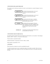
...for alerts to prevent physical or property damages to the address described in this manual. iv C141-E166 Binary number is represented normally. Decimal number is represented as "010". DANGER This indicates that either minor or moderate personal injury may have regarding this ...17B9', 17B9h or 17B9H. CONVENTIONS USED IN THIS MANUAL The MAP3147NC/NP, MAP3735NC/NP and MAP3367NC/NP disk drives are needed. Hexadecimal number is represented as "the intelligent disk drive (IDD)", "the drive" or "the device" in the sheet. ATTENTION Please forward any comments you may occur...
...for alerts to prevent physical or property damages to the address described in this manual. iv C141-E166 Binary number is represented normally. Decimal number is represented as "010". DANGER This indicates that either minor or moderate personal injury may have regarding this ...17B9', 17B9h or 17B9H. CONVENTIONS USED IN THIS MANUAL The MAP3147NC/NP, MAP3735NC/NP and MAP3367NC/NP disk drives are needed. Hexadecimal number is represented as "the intelligent disk drive (IDD)", "the drive" or "the device" in the sheet. ATTENTION Please forward any comments you may occur...
Manual/User Guide
Page 7
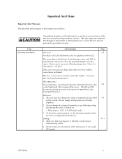
... be corrected. [Total maximum byte: 5 byte × 6 ( interleave) = 30 byte] If the error of terminals not described 5-5 in each sector where the maximum number of errors (up to the product or other property may not be performed properly. Do not connect or disconnect cables when power is off the...To short the setting terminal, use the short plug attached when the device is performed. Hot temperature To prevent injury, do not handle the drive until after the device has 5-1 cooled sufficiently after turning off the power. The user must not change the setting of read sector keeps ...
... be corrected. [Total maximum byte: 5 byte × 6 ( interleave) = 30 byte] If the error of terminals not described 5-5 in each sector where the maximum number of errors (up to the product or other property may not be performed properly. Do not connect or disconnect cables when power is off the...To short the setting terminal, use the short plug attached when the device is performed. Hot temperature To prevent injury, do not handle the drive until after the device has 5-1 cooled sufficiently after turning off the power. The user must not change the setting of read sector keeps ...
Manual/User Guide
Page 11
CONTENTS page CHAPTER 1 GENERAL DESCRIPTION 1-1 1.1 Standard Features ...1-2 1.2 Hardware Structure...1-6 1.3 System Configuration ...1-9 CHAPTER 2 SPECIFICATIONS 2-1 2.1 Hardware Specifications...2-1 2.1.1 Model name and order number 2-1 2.1.2 Function specifications...2-2 2.1.3 Environmental specifications 2-4 2.1.4 Error rate ...2-5 2.1.5 Reliability...2-5 2.2 SCSI Function Specifications 2-7 CHAPTER 3 DATA FORMAT 3-1 3.1 Data Space...3-1 3.1.1 Cylinder configuration...3-1 3.1.2 Alternate spare area...3-4 3.1.3 Track format...3-5 3.1.4 Sector format ...3-7 3.1.5 Format ...
CONTENTS page CHAPTER 1 GENERAL DESCRIPTION 1-1 1.1 Standard Features ...1-2 1.2 Hardware Structure...1-6 1.3 System Configuration ...1-9 CHAPTER 2 SPECIFICATIONS 2-1 2.1 Hardware Specifications...2-1 2.1.1 Model name and order number 2-1 2.1.2 Function specifications...2-2 2.1.3 Environmental specifications 2-4 2.1.4 Error rate ...2-5 2.1.5 Reliability...2-5 2.2 SCSI Function Specifications 2-7 CHAPTER 3 DATA FORMAT 3-1 3.1 Data Space...3-1 3.1.1 Cylinder configuration...3-1 3.1.2 Alternate spare area...3-4 3.1.3 Track format...3-5 3.1.4 Sector format ...3-7 3.1.5 Format ...
Manual/User Guide
Page 12
... 5.6.1 Confirming initial operations 5-12 5.6.2 Checking SCSI connection 5-13 5.6.3 Formatting ...5-16 5.6.4 Setting parameters ...5-18 5.7 Dismounting Drives...5-22 5.8 Spare Disk Drive ...5-22 CHAPTER 6 DIAGNOSTICS AND MAINTENANCE 6-1 6.1 Diagnostics ...6-1 6.1.1 Self-diagnostics ...6-1 6.1.2 Test programs...6-4 6.2 Maintenance Information 6-5 6.2.1 Precautions ...6-5 6.2.2 Maintenance requirements 6-6 6.2.3 Maintenance levels ...6-8 6.2.4 Revision numbers ...6-9 6.2.5 Tools and test equipment 6-10 6.2.6 Tests ...6-10 6.3 Operation Check...6-12 6.3.1 Initial seek operation check 6-12...
... 5.6.1 Confirming initial operations 5-12 5.6.2 Checking SCSI connection 5-13 5.6.3 Formatting ...5-16 5.6.4 Setting parameters ...5-18 5.7 Dismounting Drives...5-22 5.8 Spare Disk Drive ...5-22 CHAPTER 6 DIAGNOSTICS AND MAINTENANCE 6-1 6.1 Diagnostics ...6-1 6.1.1 Self-diagnostics ...6-1 6.1.2 Test programs...6-4 6.2 Maintenance Information 6-5 6.2.1 Precautions ...6-5 6.2.2 Maintenance requirements 6-6 6.2.3 Maintenance levels ...6-8 6.2.4 Revision numbers ...6-9 6.2.5 Tools and test equipment 6-10 6.2.6 Tests ...6-10 6.3 Operation Check...6-12 6.3.1 Initial seek operation check 6-12...
Manual/User Guide
Page 16
... only 5-5 CN2 setting terminal (on NP models only 5-6 Checking the SCSI connection (A 5-14 Checking the SCSI connection (B 5-15 Figure 6.1 Figure 6.2 Figure 6.3 Revision label ...6-9 Indicating revision numbers 6-10 Test flowchart...6-11 Figure 7.1 Format of extended sense data 7-2 xiv C141-E166
... only 5-5 CN2 setting terminal (on NP models only 5-6 Checking the SCSI connection (A 5-14 Checking the SCSI connection (B 5-15 Figure 6.1 Figure 6.2 Figure 6.3 Revision label ...6-9 Indicating revision numbers 6-10 Test flowchart...6-11 Figure 7.1 Format of extended sense data 7-2 xiv C141-E166
Manual/User Guide
Page 17
TABLES page Table 2.1 Model names and order numbers 2-1 Table 2.2 Function specifications ...2-2 Table 2.3 Environmental/power requirements 2-4 Table 2.4 SCSI function specifications...2-7 Table 3.1 Zone layout and track capacity 3-3 Table 3.4 Format capacity... only 5-10 Table 6.1 Self-diagnostic functions ...6-1 Table 6.2 System-level field troubleshooting 6-14 Table 6.3 Disk drive troubleshooting ...6-15 Table 7.1 Definition of sense data ...7-3 Table A.1 CN2 setting terminal (on NP model drives only A-2 Table B.1 SCSI connector (68 pin type LVD 16-bit SCSI): CN1 B-2 Table B.2 SCSI ...
TABLES page Table 2.1 Model names and order numbers 2-1 Table 2.2 Function specifications ...2-2 Table 2.3 Environmental/power requirements 2-4 Table 2.4 SCSI function specifications...2-7 Table 3.1 Zone layout and track capacity 3-3 Table 3.4 Format capacity... only 5-10 Table 6.1 Self-diagnostic functions ...6-1 Table 6.2 System-level field troubleshooting 6-14 Table 6.3 Disk drive troubleshooting ...6-15 Table 7.1 Definition of sense data ...7-3 Table A.1 CN2 setting terminal (on NP model drives only A-2 Table B.1 SCSI connector (68 pin type LVD 16-bit SCSI): CN1 B-2 Table B.2 SCSI ...
Manual/User Guide
Page 20
For the ultra SCSI model, number of connectable SCSI devices on the same SCSI bus is varied as follows. • 8-bit SCSI: 8 drives max. (option for NP model) • 16-bit SCSI: 16 drives max. (4) High speed data transfer Such a high data transfer rate on the SCSI bus can be connected directly to ...SCSI), which have the wide transfer function suitable for details of the bus width setting. This allows software to the SCSI bus of the disk drive. See subsection 5.3.2 for SCSI-2. 8-bit data bus is available only with the large capacity buffer in the standard 3.5 type fixed disk...
For the ultra SCSI model, number of connectable SCSI devices on the same SCSI bus is varied as follows. • 8-bit SCSI: 8 drives max. (option for NP model) • 16-bit SCSI: 16 drives max. (4) High speed data transfer Such a high data transfer rate on the SCSI bus can be connected directly to ...SCSI), which have the wide transfer function suitable for details of the bus width setting. This allows software to the SCSI bus of the disk drive. See subsection 5.3.2 for SCSI-2. 8-bit data bus is available only with the large capacity buffer in the standard 3.5 type fixed disk...
Manual/User Guide
Page 21
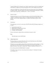
... data buffer without concerning the physical structure of the track or cylinder boundaries. Since the initiator can be achieved by specifying block number in a logically continuous data space without reaccessing the disk in case the subsequent command requests the prefetched data blocks. Data is ...blocks is surely terminated with utilizing high data transfer capability of the SCSI bus regardless of actual data transfer rate of the disk drive. (7) Cache feature After executing the READ command, the IDD reads automatically and stores (prefetches) the subsequent data blocks into the ...
... data buffer without concerning the physical structure of the track or cylinder boundaries. Since the initiator can be achieved by specifying block number in a logically continuous data space without reaccessing the disk in case the subsequent command requests the prefetched data blocks. Data is ...blocks is surely terminated with utilizing high data transfer capability of the SCSI bus regardless of actual data transfer rate of the disk drive. (7) Cache feature After executing the READ command, the IDD reads automatically and stores (prefetches) the subsequent data blocks into the ...
Manual/User Guide
Page 25
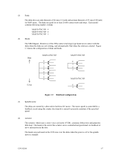
...(VCM), consumes little power and generates little heat. Figure 1.3 shows the configuration of disks. The motor speed is controlled by a direct-drive hall-less DC motor. The heads at least 20,000 contact starts and stops. The heads are good for MAP series. The disks ...zone over the disks when the power is off or the spindle motor is started. Each model contains following number of disks and heads Base Cover MAP3147NC/NP 0 1 2 3 4 5 6 7 MAP3735NC/NP 0 1 2 3 MAP3367NC/NP 0 1 Figure 1.3 Disk/head configuration (3) Spindle motor The disks are not rotating, and automatically float...
...(VCM), consumes little power and generates little heat. Figure 1.3 shows the configuration of disks. The motor speed is controlled by a direct-drive hall-less DC motor. The heads at least 20,000 contact starts and stops. The heads are good for MAP series. The disks ...zone over the disks when the power is off or the spindle motor is started. Each model contains following number of disks and heads Base Cover MAP3147NC/NP 0 1 2 3 4 5 6 7 MAP3735NC/NP 0 1 2 3 MAP3367NC/NP 0 1 Figure 1.3 Disk/head configuration (3) Spindle motor The disks are not rotating, and automatically float...
Manual/User Guide
Page 28
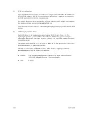
...output processing is a single logical unit, the selectable number of peripheral device Each SCSI device on the bus has its own unique address (SCSI ID:#n in Figure 1.4). The IDD is constructed so that the whole volume of disk drive is possible on which multiple host computers that operates as... or a target can be connected to the SCSI bus for the 16-bit SCSI in any combination. A unique address (LUN: logical unit number) is addressed in unit called as logical unit. For input/output operation, a peripheral device attached to select the peripheral device for each logical unit...
...output processing is a single logical unit, the selectable number of peripheral device Each SCSI device on the bus has its own unique address (SCSI ID:#n in Figure 1.4). The IDD is constructed so that the whole volume of disk drive is possible on which multiple host computers that operates as... or a target can be connected to the SCSI bus for the 16-bit SCSI in any combination. A unique address (LUN: logical unit number) is addressed in unit called as logical unit. For input/output operation, a peripheral device attached to select the peripheral device for each logical unit...
Manual/User Guide
Page 29
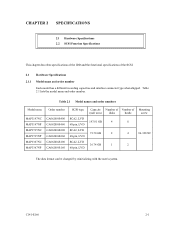
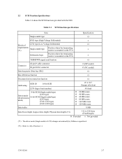
... 2.1.1 Model name and order number Each model has a different recording capacities and interface connector type when shipped. CHAPTER 2 SPECIFICATIONS 2.1 Hardware Specifications 2.2 SCSI Function Specifications This chapter describes specifications of the IDD and the functional specifications of Mounting (user area) disks heads screw 147.01 GB 4 8 73.50 GB 2 4 #6-32UNC 36.74 GB 1 2 The data format...
... 2.1.1 Model name and order number Each model has a different recording capacities and interface connector type when shipped. CHAPTER 2 SPECIFICATIONS 2.1 Hardware Specifications 2.2 SCSI Function Specifications This chapter describes specifications of the IDD and the functional specifications of Mounting (user area) disks heads screw 147.01 GB 4 8 73.50 GB 2 4 #6-32UNC 36.74 GB 1 2 The data format...
Manual/User Guide
Page 30
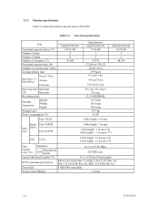
... (60 s max.) 30 s typ. 32/34 MEEPRML 25.4 mm 101.6 mm 146.0 mm 0.75 kg 9.6 W Cable length: 6 m max MAP3367NC/NP 36.74 GB 1 2 48,104 Single- Ended face Fast 20 SCSI Cable length: 3 m max Cable length: 3 m max (*6) Cable length: 1.5 m max ...drive SCSI Synchronous mode 64.1 to 528 byte (Fixed length) SCSI command specification SPI-4 (T10/1365D Rev.7), SAM-2 (T10/1157D Rev.20), SPC-2 (T10/1236D Rev.20), SBC (T10/996D Rev.8c) Data buffer 8 MB FIFO ring buffer Acostic noise (Ready) 3.4 bels 2-2 C141-E166 Table 2.2 Function specifications Item Formatted capacity/device (*1) Number...
... (60 s max.) 30 s typ. 32/34 MEEPRML 25.4 mm 101.6 mm 146.0 mm 0.75 kg 9.6 W Cable length: 6 m max MAP3367NC/NP 36.74 GB 1 2 48,104 Single- Ended face Fast 20 SCSI Cable length: 3 m max Cable length: 3 m max (*6) Cable length: 1.5 m max ...drive SCSI Synchronous mode 64.1 to 528 byte (Fixed length) SCSI command specification SPI-4 (T10/1365D Rev.7), SAM-2 (T10/1157D Rev.20), SPC-2 (T10/1236D Rev.20), SBC (T10/996D Rev.8c) Data buffer 8 MB FIFO ring buffer Acostic noise (Ready) 3.4 bels 2-2 C141-E166 Table 2.2 Function specifications Item Formatted capacity/device (*1) Number...
Manual/User Guide
Page 31
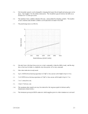
See Chapter 3 for disks to completely stop time is the time for the further information. C141-E166 2-3 The number of user cylinders and alternate cylinders can be restricted to the response speed of initiator and by changing the logical block length and using ...spare sector space. The formatted capacity listed in the table is an estimate for 512 bytes per sector. (*2) The number of user cylinders indicates the max., and includes the alternate cylinder. (*1) The formatted capacity can be specified at format of the IDD. (*3) The positioning ...
See Chapter 3 for disks to completely stop time is the time for the further information. C141-E166 2-3 The number of user cylinders and alternate cylinders can be restricted to the response speed of initiator and by changing the logical block length and using ...spare sector space. The formatted capacity listed in the table is an estimate for 512 bytes per sector. (*2) The number of user cylinders indicates the max., and includes the alternate cylinder. (*1) The formatted capacity can be specified at format of the IDD. (*3) The positioning ...
Manual/User Guide
Page 33
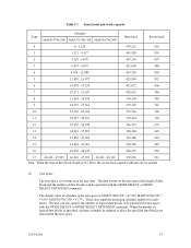
.... (*5) Input voltages are specified at all field sites The number of errors (up to 5 byte) can be recovered by alternate block assignments are applied for their ECC. Note: The MTBF is defined as: MTBF= Operating time (hours) at the drive connector side, during drive ready state. (*6) The terminator power pin (SCSI connector) which...
.... (*5) Input voltages are specified at all field sites The number of errors (up to 5 byte) can be recovered by alternate block assignments are applied for their ECC. Note: The MTBF is defined as: MTBF= Operating time (hours) at the drive connector side, during drive ready state. (*6) The terminator power pin (SCSI connector) which...
Manual/User Guide
Page 35
... model) Data bus parity (Data bus CRC) Ο Bus arbitration function Ο Disconnection/reconnection function Ο Addressing SCSI ID 16-bit SCSI LUN (logical unit number) 8-bit SCSI (Single-ended type) Data transfer (Synchronous mode) (LVD type) 16-bit SCSI (Single-ended type) (LVD type) (U160 LVD type) (U320 LVD type...
... model) Data bus parity (Data bus CRC) Ο Bus arbitration function Ο Disconnection/reconnection function Ο Addressing SCSI ID 16-bit SCSI LUN (logical unit number) 8-bit SCSI (Single-ended type) Data transfer (Synchronous mode) (LVD type) 16-bit SCSI (Single-ended type) (LVD type) (U160 LVD type) (U320 LVD type...
Manual/User Guide
Page 39
... in the user space with the MODE SELECT or MODE SELECT EXTENDED command. Table 3.1 Zone layout and track capacity Zone Cylinder MAP3147NC/NP MAP3735NC/NP MAP3367NC/NP Byte/track Sector/track 0 0 - 1,120 479,232 936 1 1,121 - 4,117 465,920 910 2 4,118 - 6,078 459,264 897 3 6,079 - 9,075 452,608 ...user space is MAP3174NC/NP = 47,589, MAP3735NC/NP = 47,645, MAP3367NC/NP = 47,771. The data format on the user space (the length of data block and the number of data blocks) can also specify the number of logical data blocks to place the specified data blocks are allocated in...
... in the user space with the MODE SELECT or MODE SELECT EXTENDED command. Table 3.1 Zone layout and track capacity Zone Cylinder MAP3147NC/NP MAP3735NC/NP MAP3367NC/NP Byte/track Sector/track 0 0 - 1,120 479,232 936 1 1,121 - 4,117 465,920 910 2 4,118 - 6,078 459,264 897 3 6,079 - 9,075 452,608 ...user space is MAP3174NC/NP = 47,589, MAP3735NC/NP = 47,645, MAP3367NC/NP = 47,771. The data format on the user space (the length of data block and the number of data blocks) can also specify the number of logical data blocks to place the specified data blocks are allocated in...
Manual/User Guide
Page 40
... parameter (saved value) • Statistical information (log data) • Controller control information The above information is duplicated in Figure 3.2. The number of 8 cylinders and outer-host cylinder is always assigned. The spare area in the Internal test space or their positions. (3) System space The...when primary cylinders in ascending order. The default for diagnostic purposes only and its data block length is always 512KByte. A number starting with 0 is assigned to the last cylinder of the last track as an alternate cylinder. The Internal test space consists...
... parameter (saved value) • Statistical information (log data) • Controller control information The above information is duplicated in Figure 3.2. The number of 8 cylinders and outer-host cylinder is always assigned. The spare area in the Internal test space or their positions. (3) System space The...when primary cylinders in ascending order. The default for diagnostic purposes only and its data block length is always 512KByte. A number starting with 0 is assigned to the last cylinder of the last track as an alternate cylinder. The Internal test space consists...
Manual/User Guide
Page 41
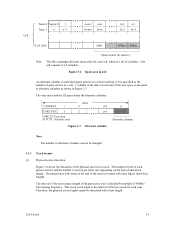
...The length in formats with a byte length. The interval of the sector pulse (length of the physical sector) is allocated as alternate cylinders as the number of spare sectors in a cell. 1 cylinder at the end of the track in bytes of each physical sector and the... Figure 3.4 shows the allocation of the physical sectors in Figure 3.3. Zone Figure 3.3 Alternate cylinder Note: The number of alternate cylinders can not be described with most logical data block lengths. Cell Note: This drive manages alternate spare areas for each cell, which is not equal to the interval of the byte...
...The length in formats with a byte length. The interval of the sector pulse (length of the physical sector) is allocated as alternate cylinders as the number of spare sectors in a cell. 1 cylinder at the end of the track in bytes of each physical sector and the... Figure 3.4 shows the allocation of the physical sectors in Figure 3.3. Zone Figure 3.3 Alternate cylinder Note: The number of alternate cylinders can not be described with most logical data block lengths. Cell Note: This drive manages alternate spare areas for each cell, which is not equal to the interval of the byte...