
Manual/User Guide
Page 5
... appendixes give supplementary information, including a list of setting items and the signal assignments of MAP series disk drive. PREFACE This manual describes the MAP3147NC/NP, MAP3735NC/NP and MAP3367NC/NP (hereafter, MAP series), 3.5 type fixed disk drives with an embedded SCSI controller. This manual details the specifications and functions of the above disk...
... appendixes give supplementary information, including a list of setting items and the signal assignments of MAP series disk drive. PREFACE This manual describes the MAP3147NC/NP, MAP3735NC/NP and MAP3367NC/NP (hereafter, MAP series), 3.5 type fixed disk drives with an embedded SCSI controller. This manual details the specifications and functions of the above disk...
Manual/User Guide
Page 6
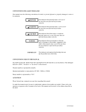
... C141-E166 Hexadecimal number is represented normally. CONVENTIONS USED IN THIS MANUAL The MAP3147NC/NP, MAP3735NC/NP and MAP3367NC/NP disk drives are needed. Binary number is represented as "the intelligent disk drive (IDD)", "the drive" or "the device" in the sheet. To make this manual and forward it to the product, equipment, data...
... C141-E166 Hexadecimal number is represented normally. CONVENTIONS USED IN THIS MANUAL The MAP3147NC/NP, MAP3735NC/NP and MAP3367NC/NP disk drives are needed. Binary number is represented as "the intelligent disk drive (IDD)", "the drive" or "the device" in the sheet. To make this manual and forward it to the product, equipment, data...
Manual/User Guide
Page 7
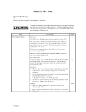
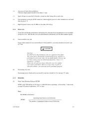
.... This alert signal also indicates that system power is turned on .(except NC model) C141-E166 v Hot temperature To prevent injury, do not handle the drive until after the device has 5-1 cooled sufficiently after turning off the power. The user must not change the setting of terminals except following setting pins...
.... This alert signal also indicates that system power is turned on .(except NC model) C141-E166 v Hot temperature To prevent injury, do not handle the drive until after the device has 5-1 cooled sufficiently after turning off the power. The user must not change the setting of terminals except following setting pins...
Manual/User Guide
Page 8
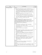
...the device. 2. Ribbon cables are used, inserting the cables in Table 4.2 are marked with the colored wire connected to clean a disk drive assembly. 5. The RECEIVE DIAGNOSTIC RESULTS command cannot read out the error information detected in the field. ESD (Electrostatics Discharge) may be ...blown or the cable may cause the damage to the cable. Caution 1. Do not remove a PCA. Fujitsu 6-7 does not assume responsibility if data is required to clean the disk drive. To connect SCSI devices, be prevented. 2. Check that the SCSI device with the CHECK CONDITION status...
...the device. 2. Ribbon cables are used, inserting the cables in Table 4.2 are marked with the colored wire connected to clean a disk drive assembly. 5. The RECEIVE DIAGNOSTIC RESULTS command cannot read out the error information detected in the field. ESD (Electrostatics Discharge) may be ...blown or the cable may cause the damage to the cable. Caution 1. Do not remove a PCA. Fujitsu 6-7 does not assume responsibility if data is required to clean the disk drive. To connect SCSI devices, be prevented. 2. Check that the SCSI device with the CHECK CONDITION status...
Manual/User Guide
Page 12
...only 5-6 5.3.2 Each mode setting (NP model only 5-7 5.3.3 Mode settings ...5-9 5.4 Mounting Drives...5-10 5.4.1 Check before mounting ...5-10 5.4.2 Mounting procedures...5-10 5.5 Connecting Cables...5-11 5.6 Confirming ...use 5-12 5.6.1 Confirming initial operations 5-12 5.6.2 Checking SCSI connection 5-13 5.6.3 Formatting ...5-16 5.6.4 Setting parameters ...5-18 5.7 Dismounting Drives...5-22 5.8 Spare Disk Drive ...5-22 CHAPTER 6 DIAGNOSTICS AND MAINTENANCE 6-1 6.1 Diagnostics ...6-1 6.1.1 Self-diagnostics ...6-1 6.1.2 Test programs...6-4 6.2 Maintenance Information 6-5 6.2.1 Precautions...
...only 5-6 5.3.2 Each mode setting (NP model only 5-7 5.3.3 Mode settings ...5-9 5.4 Mounting Drives...5-10 5.4.1 Check before mounting ...5-10 5.4.2 Mounting procedures...5-10 5.5 Connecting Cables...5-11 5.6 Confirming ...use 5-12 5.6.1 Confirming initial operations 5-12 5.6.2 Checking SCSI connection 5-13 5.6.3 Formatting ...5-16 5.6.4 Setting parameters ...5-18 5.7 Dismounting Drives...5-22 5.8 Spare Disk Drive ...5-22 CHAPTER 6 DIAGNOSTICS AND MAINTENANCE 6-1 6.1 Diagnostics ...6-1 6.1.1 Self-diagnostics ...6-1 6.1.2 Test programs...6-4 6.2 Maintenance Information 6-5 6.2.1 Precautions...
Manual/User Guide
Page 13
6.3.3 6.4 6.4.1 6.4.2 6.4.3 6.4.4 6.4.5 Diagnostic test ...6-12 Troubleshooting Procedures 6-13 Outline of troubleshooting procedures 6-13 Troubleshooting with disk drive replacement in the field 6-13 Troubleshooting at the repair site 6-15 Troubleshooting with parts replacement in the factory 6-16 Finding possibly faulty parts 6-16 CHAPTER 7 ...
6.3.3 6.4 6.4.1 6.4.2 6.4.3 6.4.4 6.4.5 Diagnostic test ...6-12 Troubleshooting Procedures 6-13 Outline of troubleshooting procedures 6-13 Troubleshooting with disk drive replacement in the field 6-13 Troubleshooting at the repair site 6-15 Troubleshooting with parts replacement in the factory 6-16 Finding possibly faulty parts 6-16 CHAPTER 7 ...
Manual/User Guide
Page 15
FIGURES Figure 1.1 Figure 1.2 Figure 1.3 Figure 1.4 page NC model drives outer view 1-6 NP model drives outer view 1-6 Disk/head configuration...1-7 System configuration ...1-9 Figure 3.1 Figure 3.2 Figure 3.3 Figure 3.4 Figure 3.5 Figure 3.6 Figure 3.7 Figure 3.8 Cylinder configuration...3-2 Spare area in cell ...3-5 Alternate cylinder ...3-5 Track format ...3-6 ...
FIGURES Figure 1.1 Figure 1.2 Figure 1.3 Figure 1.4 page NC model drives outer view 1-6 NP model drives outer view 1-6 Disk/head configuration...1-7 System configuration ...1-9 Figure 3.1 Figure 3.2 Figure 3.3 Figure 3.4 Figure 3.5 Figure 3.6 Figure 3.7 Figure 3.8 Cylinder configuration...3-2 Spare area in cell ...3-5 Alternate cylinder ...3-5 Track format ...3-6 ...
Manual/User Guide
Page 17
... check list (NP model only 5-10 Table 6.1 Self-diagnostic functions ...6-1 Table 6.2 System-level field troubleshooting 6-14 Table 6.3 Disk drive troubleshooting ...6-15 Table 7.1 Definition of sense data ...7-3 Table A.1 CN2 setting terminal (on NP model drives only A-2 Table B.1 SCSI connector (68 pin type LVD 16-bit SCSI): CN1 B-2 Table B.2 SCSI connector (SCA2 type LVD...
... check list (NP model only 5-10 Table 6.1 Self-diagnostic functions ...6-1 Table 6.2 System-level field troubleshooting 6-14 Table 6.3 Disk drive troubleshooting ...6-15 Table 7.1 Definition of sense data ...7-3 Table A.1 CN2 setting terminal (on NP model drives only A-2 Table B.1 SCSI connector (68 pin type LVD 16-bit SCSI): CN1 B-2 Table B.2 SCSI connector (SCA2 type LVD...
Manual/User Guide
Page 19
...can be changed from the format at factory shipment by reinitializing with an embedded SCSI controller. IDDs are high performance large capacity 3.5 type fixed disk drives with the user's system. C141-E166 1-1 CHAPTER 1 GENERAL DESCRIPTION 1.1 Standard Features 1.2 Hardware Structure 1.3 System Configuration This chapter describes the feature...described in the ANSI SCSI SPI-4 [T10/1365D Rev.7] to SCSI Logical Interface Specifications for details. The MAP series disk drives support the Small Computer System Interface (SCSI) as the powerful command set of the MAP series intelligent disk...
...can be changed from the format at factory shipment by reinitializing with an embedded SCSI controller. IDDs are high performance large capacity 3.5 type fixed disk drives with the user's system. C141-E166 1-1 CHAPTER 1 GENERAL DESCRIPTION 1.1 Standard Features 1.2 Hardware Structure 1.3 System Configuration This chapter describes the feature...described in the ANSI SCSI SPI-4 [T10/1365D Rev.7] to SCSI Logical Interface Specifications for details. The MAP series disk drives support the Small Computer System Interface (SCSI) as the powerful command set of the MAP series intelligent disk...
Manual/User Guide
Page 20
... Disconnection/Reconnection • Data bus parity The SCSI commands can manipulate data through logical block addressing regardless of the physical characteristics of the disk drive. 1.1 Standard Features (1) Compactness Since the SCSI controller circuit is embedded in the IDD. • 8-bit SCSI: The data transfer rate on...-bit data bus width (16-bit SCSI), which have the wide transfer function suitable for NP model) • 16-bit SCSI: 16 drives max. (4) High speed data transfer Such a high data transfer rate on the SCSI bus is 320 MB/s maximum at the paced transfer synchronous...
... Disconnection/Reconnection • Data bus parity The SCSI commands can manipulate data through logical block addressing regardless of the physical characteristics of the disk drive. 1.1 Standard Features (1) Compactness Since the SCSI controller circuit is embedded in the IDD. • 8-bit SCSI: The data transfer rate on...-bit data bus width (16-bit SCSI), which have the wide transfer function suitable for NP model) • 16-bit SCSI: 16 drives max. (4) High speed data transfer Such a high data transfer rate on the SCSI bus is 320 MB/s maximum at the paced transfer synchronous...
Manual/User Guide
Page 21
To ensure it, you turn off the drive's power. Data is transferred between SCSI bus and disk media through this data buffer. CAUTION You should issue either the SYNCHRONIZE CASHE command or the ...-segment data buffer The data buffer is 8M bytes. Since the initiator can queue maximum 128 commands, and optimizes the issuing order of the disk drive. (7) Cache feature After executing the READ command, the IDD reads automatically and stores (prefetches) the subsequent data blocks into the data buffer (Read-ahead caching...
To ensure it, you turn off the drive's power. Data is transferred between SCSI bus and disk media through this data buffer. CAUTION You should issue either the SYNCHRONIZE CASHE command or the ...-segment data buffer The data buffer is 8M bytes. Since the initiator can queue maximum 128 commands, and optimizes the issuing order of the disk drive. (7) Cache feature After executing the READ command, the IDD reads automatically and stores (prefetches) the subsequent data blocks into the data buffer (Read-ahead caching...
Manual/User Guide
Page 22
... and release functions The IDD can be accessed exclusively in the multi-host or multi-initiator environment by using its powerful retry processing. The drive format is detected during read or write the IDD can automatically reassign its alternate data block. (12) Programmable data block length Data can be...data block is generally 512 bytes at initializing with a multiple of four within the range of the drive might increase when the format would be accessed in SCSI bus or the disk drive using the reserve and release functions. (10) Error recovery The IDD can try to recover from...
... and release functions The IDD can be accessed exclusively in the multi-host or multi-initiator environment by using its powerful retry processing. The drive format is detected during read or write the IDD can automatically reassign its alternate data block. (12) Programmable data block length Data can be...data block is generally 512 bytes at initializing with a multiple of four within the range of the drive might increase when the format would be accessed in SCSI bus or the disk drive using the reserve and release functions. (10) Error recovery The IDD can try to recover from...
Manual/User Guide
Page 23
... capacity can start and stop the spindle motor. (17) Diagnosis The IDD has a diagnostic capability which checks internal controller functions and drive operations to be obtained from 3.5 type disk drives by dividing all cylinders into several partitions and changing the recording density on each partition (constant density recording). The disk subsystem with...
... capacity can start and stop the spindle motor. (17) Diagnosis The IDD has a diagnostic capability which checks internal controller functions and drive operations to be obtained from 3.5 type disk drives by dividing all cylinders into several partitions and changing the recording density on each partition (constant density recording). The disk subsystem with...
Manual/User Guide
Page 24
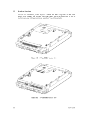
The IDD is given in Figures 1.1 and 1.2. Figure 1.1 NC model drives outer view Figure 1.2 NP model drives outer view 1-6 C141-E166 1.2 Hardware Structure An outer view of the IDD is composed of the disk, head, spindle motor, mounted disk enclosure (DE) with actuator and air circulation filter, as well as read/write pre-amp with the printed circuit assembly (PCA) of the controller.
The IDD is given in Figures 1.1 and 1.2. Figure 1.1 NC model drives outer view Figure 1.2 NP model drives outer view 1-6 C141-E166 1.2 Hardware Structure An outer view of the IDD is composed of the disk, head, spindle motor, mounted disk enclosure (DE) with actuator and air circulation filter, as well as read/write pre-amp with the printed circuit assembly (PCA) of the controller.
Manual/User Guide
Page 25
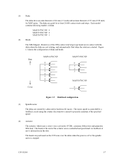
MAP3147NC/NP: 4 MAP3735NC/NP: 2 MAP3367NC/NP: 1 (2) Heads The MR (Magnet - Resistive) of the CSS (contact start/stop) type heads are in the data.... and generates little heat. Figure 1.3 shows the configuration of disks and heads Base Cover MAP3147NC/NP 0 1 2 3 4 5 6 7 MAP3735NC/NP 0 1 2 3 MAP3367NC/NP 0 1 Figure 1.3 Disk/head configuration (3) Spindle motor The disks are not rotating, and automatically float when the rotation is stopped. The heads at least 20... diameter of 25 mm (0.98 inch) for at the end of the actuator arm is controlled by a direct-drive hall-less DC motor.
MAP3147NC/NP: 4 MAP3735NC/NP: 2 MAP3367NC/NP: 1 (2) Heads The MR (Magnet - Resistive) of the CSS (contact start/stop) type heads are in the data.... and generates little heat. Figure 1.3 shows the configuration of disks and heads Base Cover MAP3147NC/NP 0 1 2 3 4 5 6 7 MAP3735NC/NP 0 1 2 3 MAP3367NC/NP 0 1 Figure 1.3 Disk/head configuration (3) Spindle motor The disks are not rotating, and automatically float when the rotation is stopped. The heads at least 20... diameter of 25 mm (0.98 inch) for at the end of the actuator arm is controlled by a direct-drive hall-less DC motor.
Manual/User Guide
Page 28
... unit. For input/output operation, a peripheral device attached to the SCSI bus that operates as target is possible on multi-SCSI devices. (2) Addressing of disk drive is assigned for each logical unit. The initiator selects one SCSI device by specifying that SCSI ID, then specifies the LUN to select the peripheral...
... unit. For input/output operation, a peripheral device attached to the SCSI bus that operates as target is possible on multi-SCSI devices. (2) Addressing of disk drive is assigned for each logical unit. The initiator selects one SCSI device by specifying that SCSI ID, then specifies the LUN to select the peripheral...
Manual/User Guide
Page 30
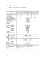
...: 3 m max Cable length: 3 m max (*6) Cable length: 1.5 m max (*7) LVD U160 Cable length: 25 m max (*8) Cable length: 12 m max (*9) Data transfer rate (*10) Disk drive SCSI Synchronous mode 64.1 to 528 byte (Fixed length) SCSI command specification SPI-4 (T10/1365D Rev.7), SAM-2 (T10/1157D Rev.20), SPC-2 (T10/1236D Rev...MAP3735NC/NP 73.50 GB 2 4 47,978 272,896 to 479,232 10,025±0.2% 2.99 msec 0.3 ms/0.5 ms 4.5 ms/5.0 ms 10.0 ms/11.0 ms 30 s typ. (60 s max.) 30 s typ. 32/34 MEEPRML 25.4 mm 101.6 mm 146.0 mm 0.75 kg 9.6 W Cable length: 6 m max MAP3367NC/NP 36.74 GB 1 2 48,104 ...
...: 3 m max Cable length: 3 m max (*6) Cable length: 1.5 m max (*7) LVD U160 Cable length: 25 m max (*8) Cable length: 12 m max (*9) Data transfer rate (*10) Disk drive SCSI Synchronous mode 64.1 to 528 byte (Fixed length) SCSI command specification SPI-4 (T10/1365D Rev.7), SAM-2 (T10/1157D Rev.20), SPC-2 (T10/1236D Rev...MAP3735NC/NP 73.50 GB 2 4 47,978 272,896 to 479,232 10,025±0.2% 2.99 msec 0.3 ms/0.5 ms 4.5 ms/5.0 ms 10.0 ms/11.0 ms 30 s typ. (60 s max.) 30 s typ. 32/34 MEEPRML 25.4 mm 101.6 mm 146.0 mm 0.75 kg 9.6 W Cable length: 6 m max MAP3367NC/NP 36.74 GB 1 2 48,104 ...
Manual/User Guide
Page 32
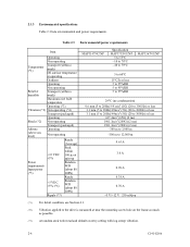
...+5 VDC ±5% (*6) Random W/R (about 80 IOPS) Ripple (*7) MAP3147NC/NP Specification MAP3735NC/NP 5 to 55°C -10 to 70°C -40 to 70°C MAP3367NC/NP 5 to 60°C 15°C/h or less 5 to 95%RH 5 to 95%RH 5 to 95%RH 29°C (no condensation) 0.6 mm (5 to 20Hz)/9.8... m to 3,000 m -300 m to 12,000 m 0.63 A 3.0 A 0.90 A 0.38 A 0.70 A +5 V/+12 V 250 mVp-p (*1) For detail condition, see Section 4.1. (*2) Vibration applied to the drive is measured at near the mounting screw hole on the frame as much as possible. (*3) At random seek write/read and default on retry setting...
...+5 VDC ±5% (*6) Random W/R (about 80 IOPS) Ripple (*7) MAP3147NC/NP Specification MAP3735NC/NP 5 to 55°C -10 to 70°C -40 to 70°C MAP3367NC/NP 5 to 60°C 15°C/h or less 5 to 95%RH 5 to 95%RH 5 to 95%RH 29°C (no condensation) 0.6 mm (5 to 20Hz)/9.8... m to 3,000 m -300 m to 12,000 m 0.63 A 3.0 A 0.90 A 0.38 A 0.70 A +5 V/+12 V 250 mVp-p (*1) For detail condition, see Section 4.1. (*2) Vibration applied to the drive is measured at near the mounting screw hole on the frame as much as possible. (*3) At random seek write/read and default on retry setting...
Manual/User Guide
Page 33
.../day, 7 days/week average DE surface temperature: 50°C or less). Note: The MTBF is defined as: MTBF= Operating time (hours) at the drive connector side, during drive ready state. (*6) The terminator power pin (SCSI connector) which cannot be 10 or less per 1015 bits. Data blocks to be accessed should be...
.../day, 7 days/week average DE surface temperature: 50°C or less). Note: The MTBF is defined as: MTBF= Operating time (hours) at the drive connector side, during drive ready state. (*6) The terminator power pin (SCSI connector) which cannot be 10 or less per 1015 bits. Data blocks to be accessed should be...
Manual/User Guide
Page 34
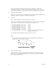
The above does not applied to diagnose and repair a drive malfunction. Therefore, the user must design the system cabinet so that the average DE surface temperature is as possible as follows. Note: The "average DE ... Time To Repair (MTTR) MTTR is the average time taken by a well-trained service mechanic to formatting disks or assigning alternate blocks. 2-6 C141-E166 The drive is 5 years.
The above does not applied to diagnose and repair a drive malfunction. Therefore, the user must design the system cabinet so that the average DE surface temperature is as possible as follows. Note: The "average DE ... Time To Repair (MTTR) MTTR is the average time taken by a well-trained service mechanic to formatting disks or assigning alternate blocks. 2-6 C141-E166 The drive is 5 years.


