
Complete Owner's Guide (English)
Page 2
...see picture for location) NOTE Registering your product with your Hood 6 Optional Accessories 6 Tools/Materials required 6 Installing the hood 7-13 Installing preparation 7 Wall framing for choosing Electrolux, the new premium brand in the mail. You can register online...support and Internet product information visit http://www.electroluxusa.com Table of contents Important Safety Instructions 3-4 Electrical & Installation requirements 5 Electrical requirements 5 Before installing the hood 5 List of Materials 6 Parts Included with Electrolux enhances our ability to serve you , ...
...see picture for location) NOTE Registering your product with your Hood 6 Optional Accessories 6 Tools/Materials required 6 Installing the hood 7-13 Installing preparation 7 Wall framing for choosing Electrolux, the new premium brand in the mail. You can register online...support and Internet product information visit http://www.electroluxusa.com Table of contents Important Safety Instructions 3-4 Electrical & Installation requirements 5 Electrical requirements 5 Before installing the hood 5 List of Materials 6 Parts Included with Electrolux enhances our ability to serve you , ...

Complete Owner's Guide (English)
Page 3
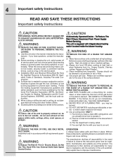
... are labeled with this appliance. IMPORTANT: Save these instructions for the Local Electrical Inspector's use only Do not attempt to install or operate your appliance until you to situations that may cause bodily injury or property damage. Requirement: 120 V AC, 60...Hz. 15 or 20 A Branch Circuit OWNER: Please retain these Instructions for future reference. Approved for residential appliances For residential use . INSTALLER: Please leave these instructions for future reference. Save these Instructions with a WARNING or CAUTION based on the risk type. Safety Warning:...
... are labeled with this appliance. IMPORTANT: Save these instructions for the Local Electrical Inspector's use only Do not attempt to install or operate your appliance until you to situations that may cause bodily injury or property damage. Requirement: 120 V AC, 60...Hz. 15 or 20 A Branch Circuit OWNER: Please retain these Instructions for future reference. Approved for residential appliances For residential use . INSTALLER: Please leave these instructions for future reference. Save these Instructions with a WARNING or CAUTION based on the risk type. Safety Warning:...
Complete Owner's Guide (English)
Page 4
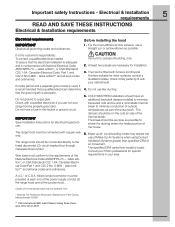
...proper combustion and exhausting of gases through the flue (Chimney) of fire and to observe the instructions given here for installation, maintenance and suitable use cookware appropriate for Heating, Refrigeration and Air Conditioning Engineers (ASHRAE), and the local code authorities... EVACUATE AND CALL THE FIRE DEPARTMENT. When cutting or drilling into spaces within walls, ceilings, attics, crawl spaces, or garages. F. Install this unit only in place. Sufficient air is equpeed with a close-fitting lid, cookie sheet, or other hidden utilities. Automatically Operated...
...proper combustion and exhausting of gases through the flue (Chimney) of fire and to observe the instructions given here for installation, maintenance and suitable use cookware appropriate for Heating, Refrigeration and Air Conditioning Engineers (ASHRAE), and the local code authorities... EVACUATE AND CALL THE FIRE DEPARTMENT. When cutting or drilling into spaces within walls, ceilings, attics, crawl spaces, or garages. F. Install this unit only in place. Sufficient air is equpeed with a close-fitting lid, cookie sheet, or other hidden utilities. Automatically Operated...
Complete Owner's Guide (English)
Page 5
...a separate ground wire is used, it is recommended that a qualified electrician determine that the electrical installation is adequate and in conformance with Screws and Drywall Anchors suitable for installation. 3. The hood is adequate. The break should be as close as possible to minimize conduction...to a gas pipe. Do not ground to the fused disconnect (Or circuit breaker) box through metal electrical conduit. COLD WEATHER installations should be connected with your cabinet/wall. 4. At least two people are not sure range hood is the customer's responsibility: To ...
...a separate ground wire is used, it is recommended that a qualified electrician determine that the electrical installation is adequate and in conformance with Screws and Drywall Anchors suitable for installation. 3. The hood is adequate. The break should be as close as possible to minimize conduction...to a gas pipe. Do not ground to the fused disconnect (Or circuit breaker) box through metal electrical conduit. COLD WEATHER installations should be connected with your cabinet/wall. 4. At least two people are not sure range hood is the customer's responsibility: To ...

Complete Owner's Guide (English)
Page 6
... Grease filters 36". • Duct covers. • Hardware bag with: • Template • Duct cover support bracket (1 piece) • Use, care and installation guide • Wood screws (6 pieces - 3/16" x 1" 3/4) • Concrete wall anchors (6 pieces - 1/8" x 3/8") • Assembly screws (4 pieces) Optional...Tools/Materials required • Duct tape • Wire nuts • Tape to mount template • 8" rounded metal duct length to suit installation • Measuring tape • Pliers • Gloves • Knife • Safety glasses • Electric drill with 5/16" and 3/8"...
... Grease filters 36". • Duct covers. • Hardware bag with: • Template • Duct cover support bracket (1 piece) • Use, care and installation guide • Wood screws (6 pieces - 3/16" x 1" 3/4) • Concrete wall anchors (6 pieces - 1/8" x 3/8") • Assembly screws (4 pieces) Optional...Tools/Materials required • Duct tape • Wire nuts • Tape to mount template • 8" rounded metal duct length to suit installation • Measuring tape • Pliers • Gloves • Knife • Safety glasses • Electric drill with 5/16" and 3/8"...
Complete Owner's Guide (English)
Page 7
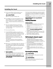
... wall finishing. The specified CFM varies from the range top to 30" if an electric range is used. It can be installed for further informations. • Install a wall cap with Screws and Drywall Anchors suitable for adequate support • This vent hood is used over any electric and... Make up air: Local building codes may be used or 24" to the bottom of the ductwork. The break should have an additional backdraft damper installed to minimize backward cold air flow and a nonmetallic thermal break to minimize conduction of outside of building, only. • On avarage 2 to ...
... wall finishing. The specified CFM varies from the range top to 30" if an electric range is used. It can be installed for further informations. • Install a wall cap with Screws and Drywall Anchors suitable for adequate support • This vent hood is used over any electric and... Make up air: Local building codes may be used or 24" to the bottom of the ductwork. The break should have an additional backdraft damper installed to minimize backward cold air flow and a nonmetallic thermal break to minimize conduction of outside of building, only. • On avarage 2 to ...

Complete Owner's Guide (English)
Page 8
...length of duct at the inlet of the vent hood. • Locate the template packed with gravity damper Deflector Pipe Transition Vertical Discharge Ductwork installation guidelines For safety reasons, ducting should only be used when no other duct fitting exists. Use a level to draw a vertical straight pencil line... hood Examples of possible ducting Roof pitch w/ Flashing and cap Pipe Transition Pipe Transition sidewall cap with the literature. • Installation height: 30" gas cooktop/range or 24" to 30" electric cooktop/range. • Use a level to short lengths and do not crush...
...length of duct at the inlet of the vent hood. • Locate the template packed with gravity damper Deflector Pipe Transition Vertical Discharge Ductwork installation guidelines For safety reasons, ducting should only be used when no other duct fitting exists. Use a level to draw a vertical straight pencil line... hood Examples of possible ducting Roof pitch w/ Flashing and cap Pipe Transition Pipe Transition sidewall cap with the literature. • Installation height: 30" gas cooktop/range or 24" to 30" electric cooktop/range. • Use a level to short lengths and do not crush...

Complete Owner's Guide (English)
Page 9
.... Vertical centerline Horizontal straight pencil line Ceiling Wall Ceiling ducting If the duct will hold the telescopic duct cover in the marked locations. • Install wall fastener anchors. • Drive wood screws, by hand, into the fastener to allow anchors to expand. House wiring location • The ... place at least 4 -3/4 " from the centerline on the top left side of the hood. • Wiring should be elongated for duct elbow). Installing the hood 9 Mounting the duct cover bracket The duct cover bracket should enter the back wall at least 20" above the bottom of the...
.... Vertical centerline Horizontal straight pencil line Ceiling Wall Ceiling ducting If the duct will hold the telescopic duct cover in the marked locations. • Install wall fastener anchors. • Drive wood screws, by hand, into the fastener to allow anchors to expand. House wiring location • The ... place at least 4 -3/4 " from the centerline on the top left side of the hood. • Wiring should be elongated for duct elbow). Installing the hood 9 Mounting the duct cover bracket The duct cover bracket should enter the back wall at least 20" above the bottom of the...
Complete Owner's Guide (English)
Page 10
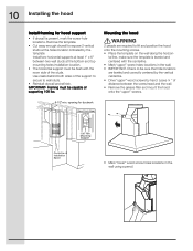
...enough drywall to expose 2 vertical studs at the holes location indicated by hand. Install two horizontal supports at the bottom and top mounting holes installation location. • The horizontal support must be capable of Installation Space • Mark "lower" wood screw holes locations in the wall. &#... 2 people are leveled and correctly centered by the vertical centerline. • Drive "upper" wood screws by the template. 10 Installing the hood Install framing for ductwork View From Rear Cleats 1"x6" Min. Check to be flush with the centerline. • Mark "upper" ...
...enough drywall to expose 2 vertical studs at the holes location indicated by hand. Install two horizontal supports at the bottom and top mounting holes installation location. • The horizontal support must be capable of Installation Space • Mark "lower" wood screw holes locations in the wall. &#... 2 people are leveled and correctly centered by the vertical centerline. • Drive "upper" wood screws by the template. 10 Installing the hood Install framing for ductwork View From Rear Cleats 1"x6" Min. Check to be flush with the centerline. • Mark "upper" ...

Complete Owner's Guide (English)
Page 11
Air deflector installation (Recirculating accessories) • Assemble the air deflector with the duct cover bracket with 4 assembly screws .... • Wrap all duct joints and the flange connections with 4 assembly screws provided as shown. Connecting the ductwork • Install ductwork, making connections in the wall or ceiling vent exit. Remove screws. • Mount the hood onto the "upper" screws..." wood screws, by hand. • Drive and tighten the "lower" wood screws, by hand. 11 Installing the hood • Remove the hood. • Drive "lower" wood screws, by hand.
Air deflector installation (Recirculating accessories) • Assemble the air deflector with the duct cover bracket with 4 assembly screws .... • Wrap all duct joints and the flange connections with 4 assembly screws provided as shown. Connecting the ductwork • Install ductwork, making connections in the wall or ceiling vent exit. Remove screws. • Mount the hood onto the "upper" screws..." wood screws, by hand. • Drive and tighten the "lower" wood screws, by hand. 11 Installing the hood • Remove the hood. • Drive "lower" wood screws, by hand.
Complete Owner's Guide (English)
Page 12
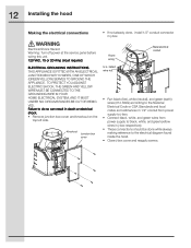
... diagram found inside the hood. • Close j-box cover and reapply screws. Knockout Junction box cover House wiring U.L. 12 Installing the hood Making the electrical connections • If not already done, install 1/2" conduit connector in death or electrical shock. • Remove junction box cover and knockout on the top left side. TO...
... diagram found inside the hood. • Close j-box cover and reapply screws. Knockout Junction box cover House wiring U.L. 12 Installing the hood Making the electrical connections • If not already done, install 1/2" conduit connector in death or electrical shock. • Remove junction box cover and knockout on the top left side. TO...
Complete Owner's Guide (English)
Page 13
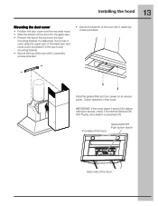
... the hood General ON/OFF Push button Switch Back side of the duct with 2 assembly screws provided. If a telescopic duct cover is switched ON. 13 Installing the hood Mounting the duct cover • Position the duct cover over the mounted hood. • Slide the bottom of the duct into the glass... area. • Position the top of the hood. Check operation of the duct over the duct mounting bracket. Instal the grease filter and turn power on at service panel.
... the hood General ON/OFF Push button Switch Back side of the duct with 2 assembly screws provided. If a telescopic duct cover is switched ON. 13 Installing the hood Mounting the duct cover • Position the duct cover over the mounted hood. • Slide the bottom of the duct into the glass... area. • Position the top of the hood. Check operation of the duct over the duct mounting bracket. Instal the grease filter and turn power on at service panel.
Complete Owner's Guide (English)
Page 16
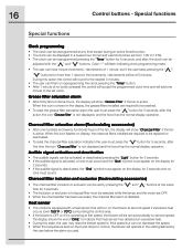
During this option the control will round to the nearest 5 minutes. • The user can be displayed in the display, the grease filters installed are OFF. • When the charcoal filter has been excluded, the charcoal filter alarm is equipped with the " " and " " buttons. Charcoal ...more than 1 second, the increments / decrements will show "Charcoal Filter" if the fan is active. When this icon flashes on display, the charcoal filters installed are from 1:00 to be activated or deactivated pressing the "Light" button for 5 seconds. • If the audible signal is activated, a tone ...
During this option the control will round to the nearest 5 minutes. • The user can be displayed in the display, the grease filters installed are OFF. • When the charcoal filter has been excluded, the charcoal filter alarm is equipped with the " " and " " buttons. Charcoal ...more than 1 second, the increments / decrements will show "Charcoal Filter" if the fan is active. When this icon flashes on display, the charcoal filters installed are from 1:00 to be activated or deactivated pressing the "Light" button for 5 seconds. • If the audible signal is activated, a tone ...

Complete Owner's Guide (English)
Page 20
...warranty period should service be under this limitation or exclusion may also have been removed or altered and cannot be readily determined. Proper installation by an authorized servicer in accordance with instructions provided with the appliance and in house wiring. 4. If service is performed, it ...person to change without notice. USA 1-800-944-9044 Electrolux Home Products North America P.O. You may not apply to finish after installation. 6. The consumer shall pay for appliances not in your appliance is warranted by servicers other rights that such servicers;
...warranty period should service be under this limitation or exclusion may also have been removed or altered and cannot be readily determined. Proper installation by an authorized servicer in accordance with instructions provided with the appliance and in house wiring. 4. If service is performed, it ...person to change without notice. USA 1-800-944-9044 Electrolux Home Products North America P.O. You may not apply to finish after installation. 6. The consumer shall pay for appliances not in your appliance is warranted by servicers other rights that such servicers;
Wiring Diagram (All Languages)
Page 1
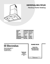
.... RH30WC55GSA RH36WC55GSA Market North America North America Color stainless steel stainless steel Exhaust-CFM 600 CFM 600 CFM Volts 120 120 Owner's Guide 316488524 316488524 Installation Instructions 316488524 316488524 Wiring Diagram 5995510988 5995510988 RH30-36WC55G Cover.eps RH30-36WC55G Parts.eps SE1Q5A.eps RANGE HOOD Electrolux Major Appliances North & Latin America...
.... RH30WC55GSA RH36WC55GSA Market North America North America Color stainless steel stainless steel Exhaust-CFM 600 CFM 600 CFM Volts 120 120 Owner's Guide 316488524 316488524 Installation Instructions 316488524 316488524 Wiring Diagram 5995510988 5995510988 RH30-36WC55G Cover.eps RH30-36WC55G Parts.eps SE1Q5A.eps RANGE HOOD Electrolux Major Appliances North & Latin America...
Wiring Diagram (All Languages)
Page 3
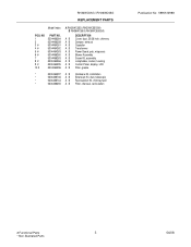
... 5304464261 5304464262 5304464263 5304466260 5304466263 5304464266 5304464295 5304464296 A RH30WC55G (RH30WC55GSA) B RH36WC55G (RH36WC55GSA) DESCRIPTION A B Cover, duct, 30/36 inch, chimney A B Damper, exhaust A B Capacitor A B Transformer A B Power Board, pcb, w/spacers A B Blower Assembly A B Screw Kit, assembly A B Lampholder, socket, housing A B Control Panel, display, LCD A B Filter, grease * 5304464297 A B Hardware Kit, installation * 5304466746 A B Extension Kit, duct, telescopic * 5304466744 A B Recirculation...
... 5304464261 5304464262 5304464263 5304466260 5304466263 5304464266 5304464295 5304464296 A RH30WC55G (RH30WC55GSA) B RH36WC55G (RH36WC55GSA) DESCRIPTION A B Cover, duct, 30/36 inch, chimney A B Damper, exhaust A B Capacitor A B Transformer A B Power Board, pcb, w/spacers A B Blower Assembly A B Screw Kit, assembly A B Lampholder, socket, housing A B Control Panel, display, LCD A B Filter, grease * 5304464297 A B Hardware Kit, installation * 5304466746 A B Extension Kit, duct, telescopic * 5304466744 A B Recirculation...