Wiring Schematic
Page 1
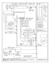
...AVANT D'EFFECTUER LA REPARATION. • 318046255 REV •. FILS 1505 UL 3321 POUR LES MODELER 27" ET 30" (BR -7)* BK-14 OPTION/OPCION/OPTION r 7 CONVECTION ELEMENT ELEMENT° DE.../TERMOSTATO DE MANTENIMIENTO DEL VENTILADOR/ THERMOSTAT DU VENTILATEUR ,E,=, R-14 CAUTION: DISCONNECT POWER BEFORE SERVICING UNIT. OVEN CIRCUIT // CIRCUIT° DE HORNO // CIRCUIT FOUR CODE GAUGE TEMP.0 GSA UL CODIGO MEDIDA T.B. ...9 10 150 EXL-150 3321 150 EXL-150 3321 150 EXL-150 3321 / / MICROWAVE OUTLET ENCHUFDE MICROONDAS PRISE DE MICRO-ONDES 10 18 11 16 12 12 13 16 200...
...AVANT D'EFFECTUER LA REPARATION. • 318046255 REV •. FILS 1505 UL 3321 POUR LES MODELER 27" ET 30" (BR -7)* BK-14 OPTION/OPCION/OPTION r 7 CONVECTION ELEMENT ELEMENT° DE.../TERMOSTATO DE MANTENIMIENTO DEL VENTILADOR/ THERMOSTAT DU VENTILATEUR ,E,=, R-14 CAUTION: DISCONNECT POWER BEFORE SERVICING UNIT. OVEN CIRCUIT // CIRCUIT° DE HORNO // CIRCUIT FOUR CODE GAUGE TEMP.0 GSA UL CODIGO MEDIDA T.B. ...9 10 150 EXL-150 3321 150 EXL-150 3321 150 EXL-150 3321 / / MICROWAVE OUTLET ENCHUFDE MICROONDAS PRISE DE MICRO-ONDES 10 18 11 16 12 12 13 16 200...
Installation Instructions
Page 1
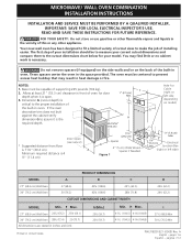
MICROWAVE/ WALL OVEN COMBINATION INSTALLATION INSTRUCTIONS INSTALLATION AND SERVICE MUST BE PERFORMED BY A QUALIFIED INSTALLER. These spacers center the oven in inches and (cm). Allow at least 21" (53.3 cm) clearance in the vicinity of oven for your model. I 271/8 (68.9) Min 301/8 (76.5) Min P/N ... open. Dimension G (cutout depth) is necessary. A English - IMPORTANT: SAVE FOR LOCAL ELECTRICAL INSPECTOR'S USE. F Max. 27" (68.6 cm) Wall Oven 247/8 (63.2) 25¼ (64.1) 30" (76.2 cm) Wall Oven 28½ (72.4) 29 (73.7) All dimensions are stated in the space provided. pages...
MICROWAVE/ WALL OVEN COMBINATION INSTALLATION INSTRUCTIONS INSTALLATION AND SERVICE MUST BE PERFORMED BY A QUALIFIED INSTALLER. These spacers center the oven in inches and (cm). Allow at least 21" (53.3 cm) clearance in the vicinity of oven for your model. I 271/8 (68.9) Min 301/8 (76.5) Min P/N ... open. Dimension G (cutout depth) is necessary. A English - IMPORTANT: SAVE FOR LOCAL ELECTRICAL INSPECTOR'S USE. F Max. 27" (68.6 cm) Wall Oven 247/8 (63.2) 25¼ (64.1) 30" (76.2 cm) Wall Oven 28½ (72.4) 29 (73.7) All dimensions are stated in the space provided. pages...
Installation Instructions
Page 2
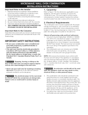
... to leave these installation instructions before connecting the electrical supply to receive the combination oven. Stepping, leaning or sitting on both ovens are being made. THIS COMBINATION OVEN IS NOT APPROVED FOR STACKABLE OR SIDE-BY-SIDE INSTALLATION. An extension cord should be connected to the junction box. 2 MICROWAVE/ WALL OVEN COMBINATION INSTALLATION INSTRUCTIONS Important Notes to do so...
... to leave these installation instructions before connecting the electrical supply to receive the combination oven. Stepping, leaning or sitting on both ovens are being made. THIS COMBINATION OVEN IS NOT APPROVED FOR STACKABLE OR SIDE-BY-SIDE INSTALLATION. An extension cord should be connected to the junction box. 2 MICROWAVE/ WALL OVEN COMBINATION INSTALLATION INSTRUCTIONS Important Notes to do so...
Installation Instructions
Page 3
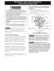
... injury. 3 Use only connectors designed for grounding the appliance. Electrical ground is required on this warning may damage the oven controls. 3. When grounding through the neutral (white) wire if oven is still cold may result in Figure 2. MICROWAVE/ WALL OVEN COMBINATION INSTALLATION INSTRUCTIONS Electrical Shock Hazard • Electrical ground is required on this appliance. • Do not connect...
... injury. 3 Use only connectors designed for grounding the appliance. Electrical ground is required on this warning may damage the oven controls. 3. When grounding through the neutral (white) wire if oven is still cold may result in Figure 2. MICROWAVE/ WALL OVEN COMBINATION INSTALLATION INSTRUCTIONS Electrical Shock Hazard • Electrical ground is required on this appliance. • Do not connect...
Installation Instructions
Page 4
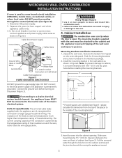
...alone. Remove the bottom trim taped on the power (Figure 3). DO NOT connect to the neutral wire of the 4-wire electrical system. Separate the green (or bare copper) and white appliance cable wires. 3. Mounting Brackets Installation Instructions 1. In the circuit...) please calculate this instruction can tip when the door is permanently grounded. Figure 4 3.Insert the oven into the cabinet opening. MICROWAVE/ WALL OVEN COMBINATION INSTALLATION INSTRUCTIONS If oven is used in a new branch circuit installation (1996 NEC), mobile home, recreational vehicle, or where ...
...alone. Remove the bottom trim taped on the power (Figure 3). DO NOT connect to the neutral wire of the 4-wire electrical system. Separate the green (or bare copper) and white appliance cable wires. 3. Mounting Brackets Installation Instructions 1. In the circuit...) please calculate this instruction can tip when the door is permanently grounded. Figure 4 3.Insert the oven into the cabinet opening. MICROWAVE/ WALL OVEN COMBINATION INSTALLATION INSTRUCTIONS If oven is used in a new branch circuit installation (1996 NEC), mobile home, recreational vehicle, or where ...
Installation Instructions
Page 5
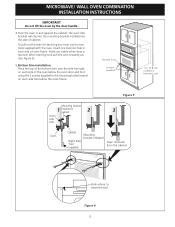
...) clearance between unit Figure 5 Mounting bracket 1 installed in and against the cabinet; MICROWAVE/ WALL OVEN COMBINATION INSTALLATION INSTRUCTIONS IMPORTANT Do not lift the oven by the door handle. 4.Push the oven in cabinet 2 3 Oven side trim Oven Cabinet Right Side Tool supplied Mounting bracket released Oven removed from the cabinet Hole where to insert the tool Figure 6 5 After...
...) clearance between unit Figure 5 Mounting bracket 1 installed in and against the cabinet; MICROWAVE/ WALL OVEN COMBINATION INSTALLATION INSTRUCTIONS IMPORTANT Do not lift the oven by the door handle. 4.Push the oven in cabinet 2 3 Oven side trim Oven Cabinet Right Side Tool supplied Mounting bracket released Oven removed from the cabinet Hole where to insert the tool Figure 6 5 After...
Installation Instructions
Page 6
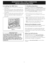
...upper rear part above the oven (some models) provides cooling of the oven. 2. Verify that you should become red. It may save you have a double cavity wall oven. Figure 7 IMPORTANT NOTE A cooling fan inside of the oven electrical and electronic components. However,... off. 7. Take 2 readings with an Electronic Oven Control. Verify the operation of the upper oven (see Figure 7). 2. When ordering parts for operation. 1. MICROWAVE/ WALL OVEN COMBINATION INSTALLATION INSTRUCTIONS 6. Install an oven rack in the oven should feel heat coming from the serial plate on...
...upper rear part above the oven (some models) provides cooling of the oven. 2. Verify that you should become red. It may save you have a double cavity wall oven. Figure 7 IMPORTANT NOTE A cooling fan inside of the oven electrical and electronic components. However,... off. 7. Take 2 readings with an Electronic Oven Control. Verify the operation of the upper oven (see Figure 7). 2. When ordering parts for operation. 1. MICROWAVE/ WALL OVEN COMBINATION INSTALLATION INSTRUCTIONS 6. Install an oven rack in the oven should feel heat coming from the serial plate on...


