Installation Instructions
Page 1
..., service agency or the gas supplier. 30" Min. * Gas Cooktop (76.2 cm) Dimensions B A C E D 2½" H (6.4 cm) G 2½" F Gas Cooktop (6.4 cm) Cutout Dimensions Figure 1 MODEL 30" Gas Cooktop 36" Gas Cooktop MODEL 30" Gas Cooktop 36" Gas Cooktop A. DEPTH D. BOX WIDTH 19 (48.3) 19 (48.3) H. pages 1-9 Español - WHAT TO DO IF YOU SMELL GAS: • Do not try to gas supply line. DEPTH BELOW COOKTOP* 8 (20.3) 8 (20.3) All...
..., service agency or the gas supplier. 30" Min. * Gas Cooktop (76.2 cm) Dimensions B A C E D 2½" H (6.4 cm) G 2½" F Gas Cooktop (6.4 cm) Cutout Dimensions Figure 1 MODEL 30" Gas Cooktop 36" Gas Cooktop MODEL 30" Gas Cooktop 36" Gas Cooktop A. DEPTH D. BOX WIDTH 19 (48.3) 19 (48.3) H. pages 1-9 Español - WHAT TO DO IF YOU SMELL GAS: • Do not try to gas supply line. DEPTH BELOW COOKTOP* 8 (20.3) 8 (20.3) All...

Installation Instructions
Page 2
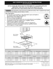
... absence, with local codes where applicable. Remove all governing codes and ordinances. 4. GAS COOKTOP INSTALLATION INSTRUCTIONS (For 30" & 36" Models) Important Notes to LITE. elevations above the cooktop. Be sure to do so could result. Observe all packing material before installing the cooktop. 2. Note: For operation at 2000 ft. IMPORTANT SAFETY INSTRUCTIONS Installation of this...
... absence, with local codes where applicable. Remove all governing codes and ordinances. 4. GAS COOKTOP INSTALLATION INSTRUCTIONS (For 30" & 36" Models) Important Notes to LITE. elevations above the cooktop. Be sure to do so could result. Observe all packing material before installing the cooktop. 2. Note: For operation at 2000 ft. IMPORTANT SAFETY INSTRUCTIONS Installation of this...
Installation Instructions
Page 3
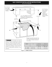
....7 cm) C. Minimum Clearance from Right Side 5" (12.7 cm) 5" (12.7 cm) Figure 2 - MODEL 30" Cooktop 36" Cooktop A 30" (76.2 cm) 36" (91.4 cm) B. GAS COOKTOP INSTALLATION INSTRUCTIONS (For 30" & 36" Models) 13" (33 cm) Max. Clearance 30" (76.2 cm) Min. Depth For Cabinet A Installed Above Cooktop. 18" Min. (45.7 cm) 1½" (3.8 cm)Minimum Distance Between Rear Edge of Countertop...
....7 cm) C. Minimum Clearance from Right Side 5" (12.7 cm) 5" (12.7 cm) Figure 2 - MODEL 30" Cooktop 36" Cooktop A 30" (76.2 cm) 36" (91.4 cm) B. GAS COOKTOP INSTALLATION INSTRUCTIONS (For 30" & 36" Models) 13" (33 cm) Max. Clearance 30" (76.2 cm) Min. Depth For Cabinet A Installed Above Cooktop. 18" Min. (45.7 cm) 1½" (3.8 cm)Minimum Distance Between Rear Edge of Countertop...

Installation Instructions
Page 4
GAS COOKTOP INSTALLATION INSTRUCTIONS (For 30" & 36" Models) Typical Under Counter Installation of supporting 150 lbs. G Side filler panels are necessary to isolate the unit from left of approved cooktop models. Must be capable of an Electric Built-in Oven with toe plate. Max. 28½" - 29.... Junction box must be located approx. 3" to the cabinets. See "Typical Gas Cooktop Installation Over an Electric Built-in Oven Installed Under the Counter" on two runners, flush with a Cooktop Mounted Above All mounting hardware must be used to secure the built-in electric...
GAS COOKTOP INSTALLATION INSTRUCTIONS (For 30" & 36" Models) Typical Under Counter Installation of supporting 150 lbs. G Side filler panels are necessary to isolate the unit from left of approved cooktop models. Must be capable of an Electric Built-in Oven with toe plate. Max. 28½" - 29.... Junction box must be located approx. 3" to the cabinets. See "Typical Gas Cooktop Installation Over an Electric Built-in Oven Installed Under the Counter" on two runners, flush with a Cooktop Mounted Above All mounting hardware must be used to secure the built-in electric...
Installation Instructions
Page 5
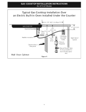
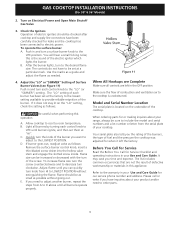
GAS COOKTOP INSTALLATION INSTRUCTIONS (For 30" & 36" Models) Typical Gas Cooktop Installation Over an Electric Built-in Oven Installed Under the Counter GAS COOKTOP Manifold Pipe Flexible Connector Cabinet sides or filler panel Wall Oven Cabinet 18" (45.7 cm) Max. 6½" 5" (16.5 cm) Flare (12.7 cm) Min. tion) 5 Union Flare Union Figure 4 4" (10.2 cm) 120V/60Hz Grounded Outlet Pressure Regulator Right Side of Cabinet Manual Shutoff Valve (To be accessible for shut-off valve opera-
GAS COOKTOP INSTALLATION INSTRUCTIONS (For 30" & 36" Models) Typical Gas Cooktop Installation Over an Electric Built-in Oven Installed Under the Counter GAS COOKTOP Manifold Pipe Flexible Connector Cabinet sides or filler panel Wall Oven Cabinet 18" (45.7 cm) Max. 6½" 5" (16.5 cm) Flare (12.7 cm) Min. tion) 5 Union Flare Union Figure 4 4" (10.2 cm) 120V/60Hz Grounded Outlet Pressure Regulator Right Side of Cabinet Manual Shutoff Valve (To be accessible for shut-off valve opera-
Installation Instructions
Page 6
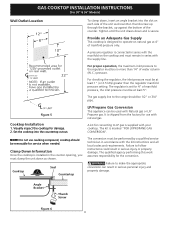
...in serious personal injury and property damage. Visually inspect the cooktop for use caulking compound; Cooktop Seal Countertop The conversion must be used with the supply line. Figure 5 Cooktop Installation 1. LP/Propane Gas Conversion This appliance can result in serious injury or property ... It is installed in series with Natural gas or LP/ Propane gas. NOTE: Do not use with your cooktop. Clamp Down Information Once the cooktop is shipped from the factory for damage. 2. GAS COOKTOP INSTALLATION INSTRUCTIONS (For 30" & 36" Models) Wall Outlet Location To clamp...
...in serious personal injury and property damage. Visually inspect the cooktop for use caulking compound; Cooktop Seal Countertop The conversion must be used with the supply line. Figure 5 Cooktop Installation 1. LP/Propane Gas Conversion This appliance can result in serious injury or property ... It is installed in series with Natural gas or LP/ Propane gas. NOTE: Do not use with your cooktop. Clamp Down Information Once the cooktop is shipped from the factory for damage. 2. GAS COOKTOP INSTALLATION INSTRUCTIONS (For 30" & 36" Models) Wall Outlet Location To clamp...
Installation Instructions
Page 7
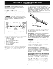
... and connections to check for leaks with Natural and LP/Propane gas to seal all connections if necessary to or less than 1/2 psig (3.5 kPa or 14"water column). GAS COOKTOP INSTALLATION INSTRUCTIONS (For 30" & 36" Models) Important: Remove all packing material and literature from the gas supply pipe to the pressure regulator in the following order...
... and connections to check for leaks with Natural and LP/Propane gas to seal all connections if necessary to or less than 1/2 psig (3.5 kPa or 14"water column). GAS COOKTOP INSTALLATION INSTRUCTIONS (For 30" & 36" Models) Important: Remove all packing material and literature from the gas supply pipe to the pressure regulator in the following order...
Installation Instructions
Page 8
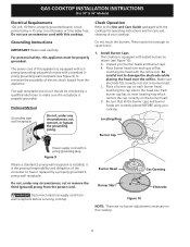
... receptacle (see Figure 10). Do not, under any circumstances, cut , remove, or bypass the grounding prong. GAS COOKTOP INSTALLATION INSTRUCTIONS (For 30" & 36" Models) Electrical Requirements 120 volt, 60 Hertz, properly grounded branch circuit protected by a properly grounded 3prong wall receptacle...third (ground) prong from wall receptacle before servicing cooktop. Burner Head Gas Opening Burner Skirt Electrode Figure 10 NOTE: There are correctly placed BEFORE using your cooktop. Install Burner Caps This cooktop is equipped with sealed burners as shown (see Figure 9) to the...
... receptacle (see Figure 10). Do not, under any circumstances, cut , remove, or bypass the grounding prong. GAS COOKTOP INSTALLATION INSTRUCTIONS (For 30" & 36" Models) Electrical Requirements 120 volt, 60 Hertz, properly grounded branch circuit protected by a properly grounded 3prong wall receptacle...third (ground) prong from wall receptacle before servicing cooktop. Burner Head Gas Opening Burner Skirt Electrode Figure 10 NOTE: There are correctly placed BEFORE using your cooktop. Install Burner Caps This cooktop is equipped with sealed burners as shown (see Figure 9) to the...
Installation Instructions
Page 9
... 3. A. B. Before You Call for Service Read the Before You Call for our service phone number and address. GAS COOKTOP INSTALLATION INSTRUCTIONS (For 30" & 36" Models) 2. Push in your cooktop. If it left in and turn to LOWEST POSITION without going out. Use the marks as a guide and adjust the ... ignite, and then set at "HI". Adjust flame until all controls are not the result of electric igniters should be checked after cooktop and supply line connectors have inquiries about your range, always be increased or decreased with the turn the knob of the burner you ...
... 3. A. B. Before You Call for Service Read the Before You Call for our service phone number and address. GAS COOKTOP INSTALLATION INSTRUCTIONS (For 30" & 36" Models) 2. Push in your cooktop. If it left in and turn to LOWEST POSITION without going out. Use the marks as a guide and adjust the ... ignite, and then set at "HI". Adjust flame until all controls are not the result of electric igniters should be checked after cooktop and supply line connectors have inquiries about your range, always be increased or decreased with the turn the knob of the burner you ...
