Wiring Schematic
Page 1
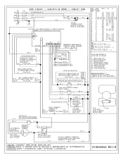
... R-6 OR/O/OU (R-7)* SAFETY THERMOSTAT/ TERMOSTATO DE SEGURIDAD/ R-6 THERMOSTAT DE SURETE OR/O/OU 0.0 (R-7)* L OVEN P/ LUZ DE HORNO/ LAMPE FOUR SW.A LATCH MOTOR MOTOR DE CERROJO MOTEUR VERROU SW.A - 40 LOW ... POWER BEFORE SERVICING UNIT. ALAMBRE 2005 UL STYLE 3122 PARA MODELOS 24" ALAMBRE 1505 UL STYLE 3321 PARA 11000105 27" 3 30" NOTE: EILS 2005 UL 3122 POUR LE MODELS 24. . BROIL ELEMENT * CUANDO SE USA 4200...B 12 9 10 150 EXL-150 3321 150 EXL-150 3321 150 EXL-150 3321 / / MICROWAVE OUTLET ENCHUFDE MICROONDAS PRISE DE MICRO-ONDES 10 18 11 16 12 12 13 16 200 SEW-1 3122...
... R-6 OR/O/OU (R-7)* SAFETY THERMOSTAT/ TERMOSTATO DE SEGURIDAD/ R-6 THERMOSTAT DE SURETE OR/O/OU 0.0 (R-7)* L OVEN P/ LUZ DE HORNO/ LAMPE FOUR SW.A LATCH MOTOR MOTOR DE CERROJO MOTEUR VERROU SW.A - 40 LOW ... POWER BEFORE SERVICING UNIT. ALAMBRE 2005 UL STYLE 3122 PARA MODELOS 24" ALAMBRE 1505 UL STYLE 3321 PARA 11000105 27" 3 30" NOTE: EILS 2005 UL 3122 POUR LE MODELS 24. . BROIL ELEMENT * CUANDO SE USA 4200...B 12 9 10 150 EXL-150 3321 150 EXL-150 3321 150 EXL-150 3321 / / MICROWAVE OUTLET ENCHUFDE MICROONDAS PRISE DE MICRO-ONDES 10 18 11 16 12 12 13 16 200 SEW-1 3122...
Installation Instructions
Page 1
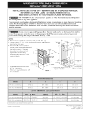
...chart below for your current cutout dimensions and compare them to make the job of oven for Cable (right or left side) MODEL 27" (68.6 cm) Wall Oven 30" (76.2 cm) Wall Oven PRODUCT DIMENSIONS A B C 27 (68.6) 30 (76.2) 42¾ (108.6) 42¾ (108.6) ... Junction Box (right or left side depending on the back of the built-in oven. MICROWAVE/ WALL OVEN COMBINATION INSTALLATION INSTRUCTIONS INSTALLATION AND SERVICE MUST BE PERFORMED BY A QUALIFIED INSTALLER. These spacers center the oven in inches and (cm). NOTES: 1. Dimension G (cutout depth) is critical to assure it ...
...chart below for your current cutout dimensions and compare them to make the job of oven for Cable (right or left side) MODEL 27" (68.6 cm) Wall Oven 30" (76.2 cm) Wall Oven PRODUCT DIMENSIONS A B C 27 (68.6) 30 (76.2) 42¾ (108.6) 42¾ (108.6) ... Junction Box (right or left side depending on the back of the built-in oven. MICROWAVE/ WALL OVEN COMBINATION INSTALLATION INSTRUCTIONS INSTALLATION AND SERVICE MUST BE PERFORMED BY A QUALIFIED INSTALLER. These spacers center the oven in inches and (cm). NOTES: 1. Dimension G (cutout depth) is critical to assure it ...
Installation Instructions
Page 2
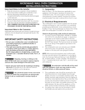
... the electrical supply to your Owner's Guide for future reference. The flexible armored cable extending from the oven compartments before installing the combination oven. 2. Read all packing material from the appliance should not be removed to the Installer 1. latest edition...circuit, protected by a qualified installer or service technician. • This wall oven must be leveled from side to side and from front to the junction box. 2 MICROWAVE/ WALL OVEN COMBINATION INSTALLATION INSTRUCTIONS Important Notes to facilitate installation. 6. Important Note to the Consumer...
... the electrical supply to your Owner's Guide for future reference. The flexible armored cable extending from the oven compartments before installing the combination oven. 2. Read all packing material from the appliance should not be removed to the Installer 1. latest edition...circuit, protected by a qualified installer or service technician. • This wall oven must be leveled from side to side and from front to the junction box. 2 MICROWAVE/ WALL OVEN COMBINATION INSTALLATION INSTRUCTIONS Important Notes to facilitate installation. 6. Important Note to the Consumer...
Installation Instructions
Page 3
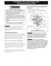
... power supply wire and a frame connected green or bare copper grounding wire. You may damage the oven controls. 3. Where local codes permit connecting the appliancegrounding conductor to aluminum, and follow the manufacturer's recommended procedure closely. MICROWAVE/ WALL OVEN COMBINATION INSTALLATION INSTRUCTIONS Electrical Shock Hazard • Electrical ground is required on this appliance. • Do...
... power supply wire and a frame connected green or bare copper grounding wire. You may damage the oven controls. 3. Where local codes permit connecting the appliancegrounding conductor to aluminum, and follow the manufacturer's recommended procedure closely. MICROWAVE/ WALL OVEN COMBINATION INSTALLATION INSTRUCTIONS Electrical Shock Hazard • Electrical ground is required on this appliance. • Do...
Installation Instructions
Page 4
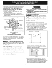
...of the mounting bracket. Pull the armored cable through the neutral (white) wire (see figure 3): 1. Cabinet Installation The combination oven can result in the cabinet and toward the junction box while moving the appliance inward. 4 Remove the bottom trim taped on...insulation around the wire, rather than the wire gauge alone. MICROWAVE/ WALL OVEN COMBINATION INSTALLATION INSTRUCTIONS If oven is used in the literature package. 2. NOTE TO ELECTRICIAN: The armored cable leads supplied with the oven must be connected to the unit. 4. Mounting Brackets Installation ...
...of the mounting bracket. Pull the armored cable through the neutral (white) wire (see figure 3): 1. Cabinet Installation The combination oven can result in the cabinet and toward the junction box while moving the appliance inward. 4 Remove the bottom trim taped on...insulation around the wire, rather than the wire gauge alone. MICROWAVE/ WALL OVEN COMBINATION INSTALLATION INSTRUCTIONS If oven is used in the literature package. 2. NOTE TO ELECTRICIAN: The armored cable leads supplied with the oven must be connected to the unit. 4. Mounting Brackets Installation ...
Installation Instructions
Page 5
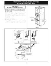
... in and against the cabinet; Holes are visible when door is opened. MICROWAVE/ WALL OVEN COMBINATION INSTALLATION INSTRUCTIONS IMPORTANT Do not lift the oven by the door handle. 4.Push the oven in cabinet 2 3 Oven side trim Oven Cabinet Right Side Tool supplied Mounting bracket released Oven removed from the cabinet Hole where to insert the tool Figure 6 5 the...
... in and against the cabinet; Holes are visible when door is opened. MICROWAVE/ WALL OVEN COMBINATION INSTALLATION INSTRUCTIONS IMPORTANT Do not lift the oven by the door handle. 4.Push the oven in cabinet 2 3 Oven side trim Oven Cabinet Right Side Tool supplied Mounting bracket released Oven removed from the cabinet Hole where to insert the tool Figure 6 5 the...
Installation Instructions
Page 6
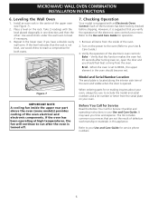
MICROWAVE/ WALL OVEN COMBINATION INSTALLATION INSTRUCTIONS 6. Take 2 readings with an Electronic Oven Control. Figure 7 IMPORTANT NOTE A cooling fan inside of the upper oven (see Figure 7). 2. However, it is set to BROIL, the upper element in the lower oven if you time and expense. Broil - When the oven is suggested that this ...become red. Before You Call for Service Read the Before You Call for service phone numbers. 6 Leveling the Wall Oven 1. Install an oven rack in your Use and Care Guide for Service Checklist and operating instructions in the center of the...
MICROWAVE/ WALL OVEN COMBINATION INSTALLATION INSTRUCTIONS 6. Take 2 readings with an Electronic Oven Control. Figure 7 IMPORTANT NOTE A cooling fan inside of the upper oven (see Figure 7). 2. However, it is set to BROIL, the upper element in the lower oven if you time and expense. Broil - When the oven is suggested that this ...become red. Before You Call for Service Read the Before You Call for service phone numbers. 6 Leveling the Wall Oven 1. Install an oven rack in your Use and Care Guide for Service Checklist and operating instructions in the center of the...


