

Complete Owner s Guide
Page 30
... gently. moved slightly. Water not cold • The water dispensing • Add ice to be below 20 psi during the regenerative phase. Drawers are too low low. (well systems only). • Connect unit to dispensing water. extended period of items in defrost • This is tightly pushed into outlet. system is set...
... gently. moved slightly. Water not cold • The water dispensing • Add ice to be below 20 psi during the regenerative phase. Drawers are too low low. (well systems only). • Connect unit to dispensing water. extended period of items in defrost • This is tightly pushed into outlet. system is set...
Wiring Diagram
Page 1
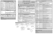
... returns to 1.2 Base Voltage 115 vac (127 vac max) DEFROST SPECIFICATIONS Cabinet Size: 26' SD, 22' CD Thermal Cutout Cut-in ) Low Side Pressure (cut -in Cut-out Heater Watts Ohms Defrost Thermis- Replace Inverter Board SYSTEM DIAGNOSTIC MODE Activate: Press FZ+ and FZ- of ...(-18° to -16°C) -1° to 3°F (-18° to -16°C) -1° to 3°F (-18° to -16°C) Refrigerator Temperature Low Side Pressure (cut -out) High Side Pressure (last 1/3 cycle) Wattage (last 1/3 cycle) Amps (running) 34° to 39°F (1° to 4°C) 5 to...
... returns to 1.2 Base Voltage 115 vac (127 vac max) DEFROST SPECIFICATIONS Cabinet Size: 26' SD, 22' CD Thermal Cutout Cut-in ) Low Side Pressure (cut -in Cut-out Heater Watts Ohms Defrost Thermis- Replace Inverter Board SYSTEM DIAGNOSTIC MODE Activate: Press FZ+ and FZ- of ...(-18° to -16°C) -1° to 3°F (-18° to -16°C) -1° to 3°F (-18° to -16°C) Refrigerator Temperature Low Side Pressure (cut -out) High Side Pressure (last 1/3 cycle) Wattage (last 1/3 cycle) Amps (running) 34° to 39°F (1° to 4°C) 5 to...

Wiring Diagram
Page 2
... 2 3 4 5 6 J4 +12V DC 7 8 +12V DC 9 GND - BLU LT. EXPLANATION IM1 12 PIN CONNECTION IN FREEZER COMPARTMENT ICEMAKER IM2 6 PIN CONNECTION TO ICEMAKER ELECTROMECHANICS LS1 9 PIN LOW SIDE EVAPORATOR COMPARTMENT MC1 12 PIN CONNECTION LEFT OF THE COMPRESSOR FZ1 6 PIN CONNECTION NEAR MAIN BOARD RH1/ LH1 2 PIN CONNECTION DOOR SWITCH DOOR FZLED...
... 2 3 4 5 6 J4 +12V DC 7 8 +12V DC 9 GND - BLU LT. EXPLANATION IM1 12 PIN CONNECTION IN FREEZER COMPARTMENT ICEMAKER IM2 6 PIN CONNECTION TO ICEMAKER ELECTROMECHANICS LS1 9 PIN LOW SIDE EVAPORATOR COMPARTMENT MC1 12 PIN CONNECTION LEFT OF THE COMPRESSOR FZ1 6 PIN CONNECTION NEAR MAIN BOARD RH1/ LH1 2 PIN CONNECTION DOOR SWITCH DOOR FZLED...

