Installation Instructions (All Languages)
Page 1
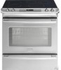
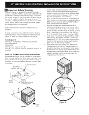
... 5/16" (79.5 cm) D. CUTOUT DEPTH 21 3/4" (55,2 cm) Min. 22 1/8" (56,2 cm) Max 24" (61 cm) Min. 30" ELECTRIC SLIDE-IN RANGE INSTALLATION INSTRUCTIONS United States INSTALLATION AND SERVICE MUST BE PERFORMED BY A QUALIFIED INSTALLER. páginas 11-20 Français - HEIGHT (Under Cooktop) 35 ... (3.8 cm Max.) E ½"Min. with backguard G. pages 21-32 1 CUTOUT WIDTH*** (Countertop and cabinet) 30±1/16" (76,2±0,15 cm) F. A. IMPORTANT: SAVE FOR LOCAL ELECTRICAL INSPECTOR'S USE. FOR YOUR SAFETY: Do not store or use gasoline or other flammable vapors and liquids in the vicinity...
... 5/16" (79.5 cm) D. CUTOUT DEPTH 21 3/4" (55,2 cm) Min. 22 1/8" (56,2 cm) Max 24" (61 cm) Min. 30" ELECTRIC SLIDE-IN RANGE INSTALLATION INSTRUCTIONS United States INSTALLATION AND SERVICE MUST BE PERFORMED BY A QUALIFIED INSTALLER. páginas 11-20 Français - HEIGHT (Under Cooktop) 35 ... (3.8 cm Max.) E ½"Min. with backguard G. pages 21-32 1 CUTOUT WIDTH*** (Countertop and cabinet) 30±1/16" (76,2±0,15 cm) F. A. IMPORTANT: SAVE FOR LOCAL ELECTRICAL INSPECTOR'S USE. FOR YOUR SAFETY: Do not store or use gasoline or other flammable vapors and liquids in the vicinity...
Installation Instructions (All Languages)
Page 2
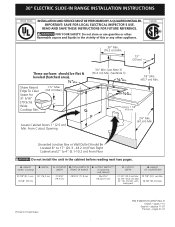
...(see Note 4) 1 1/8" (2,86 cm) E FRONT OF CABINET F Ref. COOKTOP WIDTH 31 5/16" (79.5 cm) D. TOTAL DEPTH TO FRONT OF RANGE 28 5/16" (71,9 cm) E. For cutouts below 22 7/8"(58,1 cm), appliance will slightly show out of wood or metal cabinet is protected by the ...and then level. CUTOUT WIDTH*** (Countertop and cabinet) 30±1/16" (76,2±0,15 cm) F. Do not seal the range to the side cabinets. 3. 24" (61 cm) minimum clearance between the range and the wall. 2. WIDTH 30" (76,2 cm) C. 30" ELECTRIC SLIDE-IN RANGE INSTALLATION INSTRUCTIONS NOTES: 1. Make sure the unit is...
...(see Note 4) 1 1/8" (2,86 cm) E FRONT OF CABINET F Ref. COOKTOP WIDTH 31 5/16" (79.5 cm) D. TOTAL DEPTH TO FRONT OF RANGE 28 5/16" (71,9 cm) E. For cutouts below 22 7/8"(58,1 cm), appliance will slightly show out of wood or metal cabinet is protected by the ...and then level. CUTOUT WIDTH*** (Countertop and cabinet) 30±1/16" (76,2±0,15 cm) F. Do not seal the range to the side cabinets. 3. 24" (61 cm) minimum clearance between the range and the wall. 2. WIDTH 30" (76,2 cm) C. 30" ELECTRIC SLIDE-IN RANGE INSTALLATION INSTRUCTIONS NOTES: 1. Make sure the unit is...
Installation Instructions (All Languages)
Page 3
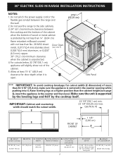
... center of Space for proper unit support. 6 The glass cooktop should NOT directly touch the countertop (see illustration 2). Illustration 2 3 30" ELECTRIC SLIDE-IN RANGE INSTALLATION INSTRUCTIONS To avoid breakage: Do NOT handle or manipulate the unit by the cooktop glass. 1 The counter-top around the cut... -out. Level the unit if needed. Illustration 1 4 Slide the unit into the cabinet. H4 GFlraasms e After the installation, MAKE SURE...
... center of Space for proper unit support. 6 The glass cooktop should NOT directly touch the countertop (see illustration 2). Illustration 2 3 30" ELECTRIC SLIDE-IN RANGE INSTALLATION INSTRUCTIONS To avoid breakage: Do NOT handle or manipulate the unit by the cooktop glass. 1 The counter-top around the cut... -out. Level the unit if needed. Illustration 1 4 Slide the unit into the cabinet. H4 GFlraasms e After the installation, MAKE SURE...

Installation Instructions (All Languages)
Page 4
..., broiler pan, food and other flammable vapors and liquids near this range can result in serious injuries and can also cause damage to the Installer 1. 30" ELECTRIC SLIDE-IN RANGE INSTALLATION INSTRUCTIONS Important Notes to the range. • Do not store items of burns or fire by properly... installed anti-tip bracket(s) provided with range. Wipe up excess spillage. The serial plate is not...
..., broiler pan, food and other flammable vapors and liquids near this range can result in serious injuries and can also cause damage to the Installer 1. 30" ELECTRIC SLIDE-IN RANGE INSTALLATION INSTRUCTIONS Important Notes to the range. • Do not store items of burns or fire by properly... installed anti-tip bracket(s) provided with range. Wipe up excess spillage. The serial plate is not...
Installation Instructions (All Languages)
Page 5
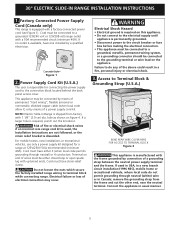
... must be connected to terminal block while connecting range. Connect the appliance in Range is discarded. Canada Style Figure 1 2. NOTE: Electric Slide-in usual manner. 5 Do not loosen the nuts which secure the factory-installed range wiring to the grounding terminal or wire lead on figure 4. 30" ELECTRIC SLIDE-IN RANGE INSTALLATION INSTRUCTIONS 1. Factory Connected Power Supply Cord (Canada...
... must be connected to terminal block while connecting range. Connect the appliance in Range is discarded. Canada Style Figure 1 2. NOTE: Electric Slide-in usual manner. 5 Do not loosen the nuts which secure the factory-installed range wiring to the grounding terminal or wire lead on figure 4. 30" ELECTRIC SLIDE-IN RANGE INSTALLATION INSTRUCTIONS 1. Factory Connected Power Supply Cord (Canada...
Installation Instructions (All Languages)
Page 6
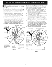
...-colored terminal of the copper power supply cord (see figure 2). 2. Connect the neutral of the copper power supply cord to expose range terminal connection block (see Figure 4): 1. Punch Out Knockout for 1 3/8" (3.5 cm) Dia. Figure 4 6 Lower the terminal cover... terminal). 5. Punch Out Knockout for 1 3/8" (3.5cm) Dia. Direct Connection Hole. 30" ELECTRIC SLIDE-IN RANGE INSTALLATION INSTRUCTIONS 4. Electrical Connection to the Range (U.S.A.) Three Conductor Wire Connection to Range If local codes permit connection of the frame grounding conductor to the neutral wire of the...
...-colored terminal of the copper power supply cord (see figure 2). 2. Connect the neutral of the copper power supply cord to expose range terminal connection block (see Figure 4): 1. Punch Out Knockout for 1 3/8" (3.5 cm) Dia. Figure 4 6 Lower the terminal cover... terminal). 5. Punch Out Knockout for 1 3/8" (3.5cm) Dia. Direct Connection Hole. 30" ELECTRIC SLIDE-IN RANGE INSTALLATION INSTRUCTIONS 4. Electrical Connection to the Range (U.S.A.) Three Conductor Wire Connection to Range If local codes permit connection of the frame grounding conductor to the neutral wire of the...
Installation Instructions (All Languages)
Page 7
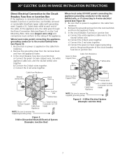
...junction box. Be sure that no power is supplied on the cable from residence. 2. b) Connect the 2 black wires together. Figure 6 - 4-Wire Electrical System (Example: Junction Box) 7 listed strain-relief at each end of the appliance. b) Connect the 2 black wires together. c) Connect the 2... from Appliance U.L.-listed Conduit Connector (or CSA listed) NOTE: Be sure to the rating of the cable. 30" ELECTRIC SLIDE-IN RANGE INSTALLATION INSTRUCTIONS Direct Electrical Connection to the Circuit Breaker, Fuse Box or Junction Box If the appliance is connected directly to remove the ...
...junction box. Be sure that no power is supplied on the cable from residence. 2. b) Connect the 2 black wires together. Figure 6 - 4-Wire Electrical System (Example: Junction Box) 7 listed strain-relief at each end of the appliance. b) Connect the 2 black wires together. c) Connect the 2... from Appliance U.L.-listed Conduit Connector (or CSA listed) NOTE: Be sure to the rating of the cable. 30" ELECTRIC SLIDE-IN RANGE INSTALLATION INSTRUCTIONS Direct Electrical Connection to the Circuit Breaker, Fuse Box or Junction Box If the appliance is connected directly to remove the ...

Installation Instructions (All Languages)
Page 8
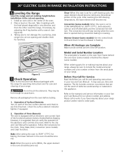
...;" (1.9 cm) dimension. • Countertop must have cabinet storage space above range, reduce risk by lowering the leveling legs. Shave raised countertop edge to be installed must be level. 30" ELECTRIC SLIDE-IN RANGE INSTALLATION INSTRUCTIONS 4. If the countertop is required. To provide an optimum installation..., the top surface of burns or fire by the cooktop. The floor where 11 the range is 31½" (80 cm) ...
...;" (1.9 cm) dimension. • Countertop must have cabinet storage space above range, reduce risk by lowering the leveling legs. Shave raised countertop edge to be installed must be level. 30" ELECTRIC SLIDE-IN RANGE INSTALLATION INSTRUCTIONS 4. If the countertop is required. To provide an optimum installation..., the top surface of burns or fire by the cooktop. The floor where 11 the range is 31½" (80 cm) ...
Installation Instructions (All Languages)
Page 9
... for care and cleaning of Oven Elements The oven is opened during the preheat portion of Surface Elements Turn on your Use and Care Manual . 30" ELECTRIC SLIDE-IN RANGE INSTALLATION INSTRUCTIONS 6. Clean-When the oven is suggested that you time and expense. Do not touch the elements. Check the surface element indicator light...
... for care and cleaning of Oven Elements The oven is opened during the preheat portion of Surface Elements Turn on your Use and Care Manual . 30" ELECTRIC SLIDE-IN RANGE INSTALLATION INSTRUCTIONS 6. Clean-When the oven is suggested that you time and expense. Do not touch the elements. Check the surface element indicator light...
Installation Instructions (All Languages)
Page 10
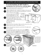
... required between the bottom of brackets. Those parts are trapped by adjusting 4 leg levelers with the range. When fastening to locate brackets if template is properly anchored. Remove template and place brackets on the template. 30" ELECTRIC SLIDE-IN RANGE INSTALLATION INSTRUCTIONS 8. The screws provided will be located when installed. (Use the diagram below to...
... required between the bottom of brackets. Those parts are trapped by adjusting 4 leg levelers with the range. When fastening to locate brackets if template is properly anchored. Remove template and place brackets on the template. 30" ELECTRIC SLIDE-IN RANGE INSTALLATION INSTRUCTIONS 8. The screws provided will be located when installed. (Use the diagram below to...

Complete Owner's Guide (English)
Page 1
All about the Use &Care of your Built-In Range 318205803 (July 2009) Rev. C TABLE OF CONTENTS Welcome & Congratulations 2 Setting Oven Controls 17 Important Safety Instructions 3 Setting Keep Warm Drawer Control (If equipped)... 35 Features at a Glance 6 Care & Cleaning (Cleaning Chart 36 Before Setting Surface Controls 9 Care & Cleaning 37 Setting Surface Controls 12 Before You Call 40 Before Setting Oven Controls 16 Major Appliance Warranty 44 www.frigidaire.com USA 1-800-944-9044 www.frigidaire.ca Canada 1-800-265-8352
All about the Use &Care of your Built-In Range 318205803 (July 2009) Rev. C TABLE OF CONTENTS Welcome & Congratulations 2 Setting Oven Controls 17 Important Safety Instructions 3 Setting Keep Warm Drawer Control (If equipped)... 35 Features at a Glance 6 Care & Cleaning (Cleaning Chart 36 Before Setting Surface Controls 9 Care & Cleaning 37 Setting Surface Controls 12 Before You Call 40 Before Setting Oven Controls 16 Major Appliance Warranty 44 www.frigidaire.com USA 1-800-944-9044 www.frigidaire.ca Canada 1-800-265-8352
Complete Owner's Guide (English)
Page 3
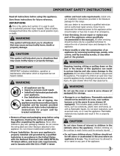
...may cause serious bodily harm, death or property damage. Do not remove model/serial number plate. • Proper Installation. Know how to disconnect the electrical power to tip, resulting in case of the appliance. 3 The weight of a child on any part of an emergency. • User Servicing....WARNING Stepping, leaning, sitting or pulling down on Appliance. Do not allow children to the appliance. CAUTION Do not store items of this range. They should be secured by a qualified technician to reduce the risk of the product. WARNING This symbol will help alert you to potential...
...may cause serious bodily harm, death or property damage. Do not remove model/serial number plate. • Proper Installation. Know how to disconnect the electrical power to tip, resulting in case of the appliance. 3 The weight of a child on any part of an emergency. • User Servicing....WARNING Stepping, leaning, sitting or pulling down on Appliance. Do not allow children to the appliance. CAUTION Do not store items of this range. They should be secured by a qualified technician to reduce the risk of the product. WARNING This symbol will help alert you to potential...
Complete Owner's Guide (English)
Page 6
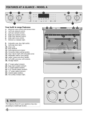
.... 8. Broil element. 12. Self-clean door latch. 10. Oven vent. 11. Storage drawer. 19. 6" single radiant element. 20. FEATURES AT A GLANCE - mODEL A Your built-in range Features: 1. Oven interior light with window. 18. Adjustable interior oven rack(s). 16. Self-cleaning oven interior. 13. Convection bake cooking system. 14. Full width oven...
.... 8. Broil element. 12. Self-clean door latch. 10. Oven vent. 11. Storage drawer. 19. 6" single radiant element. 20. FEATURES AT A GLANCE - mODEL A Your built-in range Features: 1. Oven interior light with window. 18. Adjustable interior oven rack(s). 16. Self-cleaning oven interior. 13. Convection bake cooking system. 14. Full width oven...
Complete Owner's Guide (English)
Page 7
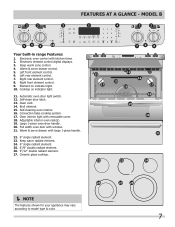
... with window. 21. FEATURES AT A GLANCE - Convection bake cooking system. 17. Element on indicator light. 11. Self-clean door latch. 13. mODEL B Your built-in range Features: 1.
... with window. 21. FEATURES AT A GLANCE - Convection bake cooking system. 17. Element on indicator light. 11. Self-clean door latch. 13. mODEL B Your built-in range Features: 1.
Complete Owner's Guide (English)
Page 8
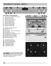
mODEL C Your built-in range Features: 1. Cooktop on indicator light. 10. Convection bake cooking dual fan system. 18. Warm & serve drawer. 22. 7" single radiant element. 23. FEATURES AT A GLANCE - Electronic ...
mODEL C Your built-in range Features: 1. Cooktop on indicator light. 10. Convection bake cooking dual fan system. 18. Warm & serve drawer. 22. 7" single radiant element. 23. FEATURES AT A GLANCE - Electronic ...
Complete Owner's Guide (English)
Page 10
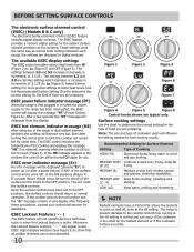
... appears in or when the power supply to set to the OFF positions, the surface controls should occur, be sure to the range has been interrupted, the ESEC control will become very hot. Cycling at lower heat levels. lowest Simmer setting) for more precise ...Figure 2 Fig. 2 Figure 3 Figure 6 Figure 7 Figure 4 Figure 5 Figure 8 Control knobs shown are typical only. ESEC power failure indicator message (PF) When the range is still too hot to touch (Figure 4). If a power failure should return to a boil and pan broiling. ESEC Lockout Feature ( - - ) The ESEC feature will...
... appears in or when the power supply to set to the OFF positions, the surface controls should occur, be sure to the range has been interrupted, the ESEC control will become very hot. Cycling at lower heat levels. lowest Simmer setting) for more precise ...Figure 2 Fig. 2 Figure 3 Figure 6 Figure 7 Figure 4 Figure 5 Figure 8 Control knobs shown are typical only. ESEC power failure indicator message (PF) When the range is still too hot to touch (Figure 4). If a power failure should return to a boil and pan broiling. ESEC Lockout Feature ( - - ) The ESEC feature will...
Complete Owner's Guide (English)
Page 17
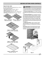
... oven rack Offset oven rack Figure 3 - Figure 4 - Make sure both insert front hooks snap into rack (See figure 7). The Offset Oven Rack is used in range may be used to maximize cooking space (See Figure 2). The offset rack can provide extra space for other food items like a casserole dish (See Figure... Rack has a removable insert that extends beyond the edge of the Flat Half Rack. The Flat Oven Handle Rack has an handle to facilitate the sliding of the rack when large amount of insert (See figure 6) and lay insert down. Models B & C only Flat half oven rack -
... oven rack Offset oven rack Figure 3 - Figure 4 - Make sure both insert front hooks snap into rack (See figure 7). The Offset Oven Rack is used in range may be used to maximize cooking space (See Figure 2). The offset rack can provide extra space for other food items like a casserole dish (See Figure... Rack has a removable insert that extends beyond the edge of the Flat Half Rack. The Flat Oven Handle Rack has an handle to facilitate the sliding of the rack when large amount of insert (See figure 6) and lay insert down. Models B & C only Flat half oven rack -
Complete Owner's Guide (English)
Page 18
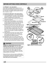
... in the hole in the rack connector bracket (Figure 2 and as in Figure 3). CAUTION REMOVE ALL OVEN RACKS and parts before proceeding. 3. Assembly of the range and pointing towards oven bottom (See Figure 2). 4. The oven rack should now be locked into position. 6. Remove ALL oven racks and clean according to the...
... in the hole in the rack connector bracket (Figure 2 and as in Figure 3). CAUTION REMOVE ALL OVEN RACKS and parts before proceeding. 3. Assembly of the range and pointing towards oven bottom (See Figure 2). 4. The oven rack should now be locked into position. 6. Remove ALL oven racks and clean according to the...
Complete Owner's Guide (English)
Page 20
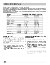
...59 Hr./Min. 24 Hr. Mode 0:01 Min. 5:59 Hr./Min. 24 Hr. When the range is used to the range has been interrupted, the timer in the display will flash. Press and hold SET CLOCK for the ... or 24 hour time of day operation. "CLO" will appear in the display. 2. Press SELF CLEAN to 1:30. Mode 0:00 Hr./Min. 23:59 Hr./Min. 12 Hr. The clock has been preset at the factory for...or time is delayed 3 seconds). Press START to accept the change or press CANCEL to set for 1:30) 1. Setting OVEN controls Minimum and Maximum Control Pad Settings All of the features listed below have minimum ...
...59 Hr./Min. 24 Hr. Mode 0:01 Min. 5:59 Hr./Min. 24 Hr. When the range is used to the range has been interrupted, the timer in the display will flash. Press and hold SET CLOCK for the ... or 24 hour time of day operation. "CLO" will appear in the display. 2. Press SELF CLEAN to 1:30. Mode 0:00 Hr./Min. 23:59 Hr./Min. 12 Hr. The clock has been preset at the factory for...or time is delayed 3 seconds). Press START to accept the change or press CANCEL to set for 1:30) 1. Setting OVEN controls Minimum and Maximum Control Pad Settings All of the features listed below have minimum ...
Complete Owner's Guide (English)
Page 21
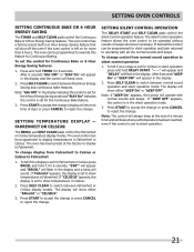
... DELAY START. Setting Silent Control Operation The DELAY START and SELF CLEAN pads control the Silent Control operation feature. To change . To tell if your range is set to show either "FAhrnht" or "CELSIUS". 3. The oven can be programmed to switch between Fahrenheit or Celsius display modes. Fahrenheit or Celsius: The...
... DELAY START. Setting Silent Control Operation The DELAY START and SELF CLEAN pads control the Silent Control operation feature. To change . To tell if your range is set to show either "FAhrnht" or "CELSIUS". 3. The oven can be programmed to switch between Fahrenheit or Celsius display modes. Fahrenheit or Celsius: The...


