Complete Owners Guide
Page 5
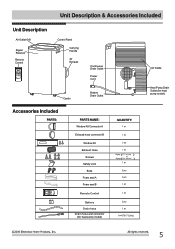
Unit Description & Accessories Included Unit Description Air Outlet Grill Signal Receiver Remote Control Control Panel Carrying Handle Air Exhaust Continuous Drain Outlet Power Cord Castor Bottom Drain Outlet Accessories Included PARTS: PARTS NAME: Window Kit Connector A Exhaust hose connector B Window Kit Exhaust Hose Screws Safety Lock Bolts Foam seal A Foam seal B Remote Control Battery Drain hose Drain hose and connector (for heat pump model) QUANTITY: ( ) + ( ) (78.7"(2m)) Air Intake Heat Pump Drain Outlet (for heat pump model)
Unit Description & Accessories Included Unit Description Air Outlet Grill Signal Receiver Remote Control Control Panel Carrying Handle Air Exhaust Continuous Drain Outlet Power Cord Castor Bottom Drain Outlet Accessories Included PARTS: PARTS NAME: Window Kit Connector A Exhaust hose connector B Window Kit Exhaust Hose Screws Safety Lock Bolts Foam seal A Foam seal B Remote Control Battery Drain hose Drain hose and connector (for heat pump model) QUANTITY: ( ) + ( ) (78.7"(2m)) Air Intake Heat Pump Drain Outlet (for heat pump model)
Complete Owners Guide
Page 6
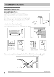
...Extend both side of the unit. 1. Install the connector B into the window slider kit and seal.(Fig.3&4) 19.7" 31.5" 2 Lock 1 Slide onto Extend the side of hose Fig.1 Fig.2 Vertical window Window Slider Kit Minimum:26.6 (67.5cm) Maxmum:52.5 (133cm) Fig.3 Horizontal window Window Slider Kit Minimum:26.6 (67.5cm) Maxmum:52.5 (133cm) Fig.4 The ... a flat floor and is within the vicinity of 15"up to 59",but it is the best to keep the length to a window or opening so that the hose does not have any sharp bends or sags.(Fig.5) Fig.5 Affix the connector A into the unit (Fig.2). 3....
...Extend both side of the unit. 1. Install the connector B into the window slider kit and seal.(Fig.3&4) 19.7" 31.5" 2 Lock 1 Slide onto Extend the side of hose Fig.1 Fig.2 Vertical window Window Slider Kit Minimum:26.6 (67.5cm) Maxmum:52.5 (133cm) Fig.3 Horizontal window Window Slider Kit Minimum:26.6 (67.5cm) Maxmum:52.5 (133cm) Fig.4 The ... a flat floor and is within the vicinity of 15"up to 59",but it is the best to keep the length to a window or opening so that the hose does not have any sharp bends or sags.(Fig.5) Fig.5 Affix the connector A into the unit (Fig.2). 3....
Complete Owners Guide
Page 7
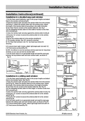
... shown(Fig.16). screws Foam seal A (adhesive type) Fig.6 Window slider kit 26.6"~52.5" Window stool Fig.7 Cut this to the window stool. Attach the window slider kit to fit your window Fig.8 Foam seal A (adhesive type) Window stool 26.6"~52.5" Fig.12 Window slider kit screws Fig.13 Window stool Window slider kit screws screws Fig.14 Foam seal B Fig.15 Fig...
... shown(Fig.16). screws Foam seal A (adhesive type) Fig.6 Window slider kit 26.6"~52.5" Window stool Fig.7 Cut this to the window stool. Attach the window slider kit to fit your window Fig.8 Foam seal A (adhesive type) Window stool 26.6"~52.5" Fig.12 Window slider kit screws Fig.13 Window stool Window slider kit screws screws Fig.14 Foam seal B Fig.15 Fig...
Complete Owners Guide
Page 17
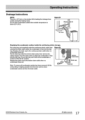
... residue inside the unit during the heating mode. Bottom Drain Outlet Drip tray Do not drain condensate outside when outside temperature is a 1/4" hole on the window kit for leading the drainage hose outside during winter storage. Put a drip tray (not supplied) under the bottom drain outlet, then remove the rubber stopper from...
... residue inside the unit during the heating mode. Bottom Drain Outlet Drip tray Do not drain condensate outside when outside temperature is a 1/4" hole on the window kit for leading the drainage hose outside during winter storage. Put a drip tray (not supplied) under the bottom drain outlet, then remove the rubber stopper from...


