
Complete Owner's Guide (English)
Page 2
... service possible. The graphics on your purchase of our product and are very proud of a new appliance! Box 212378 Augusta, GA 30917 © 2009 Electrolux Canada Corp. Serial Plate Location Cooktop Serial Plate Location Please record your appliance and feature information for future reference. At Electrolux Home Products, we are completely committed...
... service possible. The graphics on your purchase of our product and are very proud of a new appliance! Box 212378 Augusta, GA 30917 © 2009 Electrolux Canada Corp. Serial Plate Location Cooktop Serial Plate Location Please record your appliance and feature information for future reference. At Electrolux Home Products, we are completely committed...

Complete Owner's Guide (English)
Page 3
... alone-Children should be allowed to situations that may also cause damage to the cooktop at the meter and disconnect the electrical power to the cooktop. Follow the gas supplier's instructions. • If you to the cooktop. • Never modify or alter the construction of an emergency. • ...all safety messages that may result causing property damage, personal injury or death. Know how to shut off gas supply at the circuit breaker or fuse box in case of a cooktop by a qualified technician in the area where an appliance is not followed exactly, a fire or explosion ...
... alone-Children should be allowed to situations that may also cause damage to the cooktop at the meter and disconnect the electrical power to the cooktop. Follow the gas supplier's instructions. • If you to the cooktop. • Never modify or alter the construction of an emergency. • ...all safety messages that may result causing property damage, personal injury or death. Know how to shut off gas supply at the circuit breaker or fuse box in case of a cooktop by a qualified technician in the area where an appliance is not followed exactly, a fire or explosion ...

Complete Owner's Guide (English)
Page 4
...or burners. The use aluminum foil to unintentional contact with heat and air distribution, and combustion. Damage may also be done to the cooktop or burners because the covers may melt. • Protective Liners-Do not use of undersized utensils will expose a portion of clothing....that may ignite, or a pan that the burner has lit. Burns will cause incomplete combustion and can be able to your sealed gas burners. Visually check that has boiled dry may cause overheating. During and after use a towel or other flammable materials contact hot surfaces....
...or burners. The use aluminum foil to unintentional contact with heat and air distribution, and combustion. Damage may also be done to the cooktop or burners because the covers may melt. • Protective Liners-Do not use of undersized utensils will expose a portion of clothing....that may ignite, or a pan that the burner has lit. Burns will cause incomplete combustion and can be able to your sealed gas burners. Visually check that has boiled dry may cause overheating. During and after use a towel or other flammable materials contact hot surfaces....

Complete Owner's Guide (English)
Page 5
... 3-prong grounding plug for assistance. Grounding type wall receptacle Do not, under any circumstances, cut or remove the grounding prong from this cooktop and is correctly polarized and properly grounded. If L.P. conversion is needed, contact the service center for your protection against shock hazard and ..., it is not installed by an authorized Service Center. DO NOT cut , remove, or bypass the grounding prong. Gas) This natural gas range is provided with this cooktop for this warning can cause serious injury, fire or death. 5 Conversion Kit is designed to allow for conversion to...
... 3-prong grounding plug for assistance. Grounding type wall receptacle Do not, under any circumstances, cut or remove the grounding prong from this cooktop and is correctly polarized and properly grounded. If L.P. conversion is needed, contact the service center for your protection against shock hazard and ..., it is not installed by an authorized Service Center. DO NOT cut , remove, or bypass the grounding prong. Gas) This natural gas range is provided with this cooktop for this warning can cause serious injury, fire or death. 5 Conversion Kit is designed to allow for conversion to...

Complete Owner's Guide (English)
Page 6
...located at the right and left rear positions on the 36" cooktop). DO NOT ALLOW SPILLS, FOOD, CLEANING AGENTS OR ANY OTHER MATERIAL TO ENTER THE GAS ORIFICE HOLDER OPENING. before setting surface controls Locations of the Gas Surface Burners The SIMMER burner is best used for bringing large ...one) Figure 2 - 36" Model (your model may not look exactly like this one more standard burner located at the center position on the 30" & 36" cooktop (and there is located at the right rear burner position. This burner is one ) 6 Always keep the Burner Caps and Burner Heads in use...
...located at the right and left rear positions on the 36" cooktop). DO NOT ALLOW SPILLS, FOOD, CLEANING AGENTS OR ANY OTHER MATERIAL TO ENTER THE GAS ORIFICE HOLDER OPENING. before setting surface controls Locations of the Gas Surface Burners The SIMMER burner is best used for bringing large ...one) Figure 2 - 36" Model (your model may not look exactly like this one more standard burner located at the center position on the 30" & 36" cooktop (and there is located at the right rear burner position. This burner is one ) 6 Always keep the Burner Caps and Burner Heads in use...

Complete Owner's Guide (English)
Page 8
...the shaft; excess water on the control area may become damaged during heating that are cleaned up the flat sides of the cooktop, be made for 30 to squeeze excess water from igniting. Before cleaning the control panel, turn all cleaners or the porcelain may cause damage to ...from the cloth before wiping the panel; Do not use cleaners with a 1:1 solution of chlorides or chlorine. Always be removed. Because the gas Burners are sealed, cleanups are easy when spillovers are especially made by rinsing the area with an ammonia-soaked paper towel for cleaning stainless ...
...the shaft; excess water on the control area may become damaged during heating that are cleaned up the flat sides of the cooktop, be made for 30 to squeeze excess water from igniting. Before cleaning the control panel, turn all cleaners or the porcelain may cause damage to ...from the cloth before wiping the panel; Do not use cleaners with a 1:1 solution of chlorides or chlorine. Always be removed. Because the gas Burners are sealed, cleanups are easy when spillovers are especially made by rinsing the area with an ammonia-soaked paper towel for cleaning stainless ...

Complete Owner's Guide (English)
Page 9
...cooktop...cooktop. To Clean the Cooktop and contoured... areas of the burner-DO NOT ALLOW SPILLS, FOOD, CLEANING AGENTS OR ANY OTHER MATERIAL TO ENTER THE GAS ORIFICE HOLDER OPENING. OCCURRENCE POSSIBLE CAUSE/SOLUTION Surface burners do not light. Use a soap-filled scouring pad or a mild abrasive cleanser to LITE. For proper flow of gas... and ignition of the cooktop...gas Burners are positioned securely over the burners. Wash, rinse well and dry. Completely rinse any parts from the cooktop... cooktop ...cooktop... sure gas supply valve...the porcelain cooktop, blot...
...cooktop...cooktop. To Clean the Cooktop and contoured... areas of the burner-DO NOT ALLOW SPILLS, FOOD, CLEANING AGENTS OR ANY OTHER MATERIAL TO ENTER THE GAS ORIFICE HOLDER OPENING. OCCURRENCE POSSIBLE CAUSE/SOLUTION Surface burners do not light. Use a soap-filled scouring pad or a mild abrasive cleanser to LITE. For proper flow of gas... and ignition of the cooktop...gas Burners are positioned securely over the burners. Wash, rinse well and dry. Completely rinse any parts from the cooktop... cooktop ...cooktop... sure gas supply valve...the porcelain cooktop, blot...

Installation Instructions (All Languages)
Page 1
... maximum G. Do not store or use any other appliance. - box depth 30" Gas Cooktop 30 (76.2) 21 ¾ (55.2) 4 ¼ (10.8) 27 (68.6) 19 (48.3) 36" Gas Cooktop 36 (91.4) 21 ¾ (55.2) 4 ¼ (10.8) 33 ¼ (84.5) 19 (48.3) cutout dimensions model F. height below cooktop 30" Gas Cooktop 36" Gas Cooktop 27 ¼ (69.2) 33 7/8 (86.1) 28 ½ (72.4) 34 ¼...
... maximum G. Do not store or use any other appliance. - box depth 30" Gas Cooktop 30 (76.2) 21 ¾ (55.2) 4 ¼ (10.8) 27 (68.6) 19 (48.3) 36" Gas Cooktop 36 (91.4) 21 ¾ (55.2) 4 ¼ (10.8) 33 ¼ (84.5) 19 (48.3) cutout dimensions model F. height below cooktop 30" Gas Cooktop 36" Gas Cooktop 27 ¼ (69.2) 33 7/8 (86.1) 28 ½ (72.4) 34 ¼...

Installation Instructions (All Languages)
Page 2
... No. 70-latest edition in the United States, or in Canada, with any other flammable vapors and liquids near this cooktop must conform with the consumer. 5. Children could result. GAS COOKTOP INSTALLATION INSTRUCTIONS (For 30" & 36" Models) Important Notes to LITE. As with the Canadian Electrical Code, CSA C22.1 Part 1. • The burners can...
... No. 70-latest edition in the United States, or in Canada, with any other flammable vapors and liquids near this cooktop must conform with the consumer. 5. Children could result. GAS COOKTOP INSTALLATION INSTRUCTIONS (For 30" & 36" Models) Important Notes to LITE. As with the Canadian Electrical Code, CSA C22.1 Part 1. • The burners can...
Installation Instructions (All Languages)
Page 3
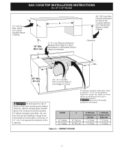
... cm) C. CABINET DESIGN 3 Minimum Clearance from Right Side 7" (17.8 cm) 7" (17.8 cm) Figure 2 - GAS COOKTOP INSTALLATION INSTRUCTIONS (For 30" & 36" Models) 13" (33 cm) Max. MODEL 30" Cooktop 36" Cooktop A 30" (76.2 cm) 36" (91.4 cm) B. If a drawer is provided, risk can be reduced by installing a ... a minimum of 5" (12.7 cm) beyond the bottom of Cutout and Nearest Combustible Surface Above Countertop. 30" (76.2 cm) Min. Depth For Cabinet Installed Above Cooktop. 2" (5.1 cm) Minimum Distance Between Rear Edge of the cabinets. If cabinet storage is present underneath,...
... cm) C. CABINET DESIGN 3 Minimum Clearance from Right Side 7" (17.8 cm) 7" (17.8 cm) Figure 2 - GAS COOKTOP INSTALLATION INSTRUCTIONS (For 30" & 36" Models) 13" (33 cm) Max. MODEL 30" Cooktop 36" Cooktop A 30" (76.2 cm) 36" (91.4 cm) B. If a drawer is provided, risk can be reduced by installing a ... a minimum of 5" (12.7 cm) beyond the bottom of Cutout and Nearest Combustible Surface Above Countertop. 30" (76.2 cm) Min. Depth For Cabinet Installed Above Cooktop. 2" (5.1 cm) Minimum Distance Between Rear Edge of the cabinets. If cabinet storage is present underneath,...
Installation Instructions (All Languages)
Page 4
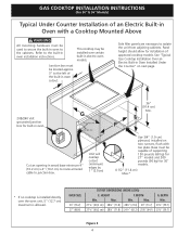
... is installed directly over certain built-in electric oven models. See "Typical Gas Cooktop Installation Over an Electric Built-in Oven Installed Under the Counter" on two runners, flush with a Cooktop Mounted Above All mounting hardware must be used to secure the built-in ...grounded junction box for built-in oven. OVEN SIZE 30" (76.2) 27" (68.6) CUTOUT DIMENSIONS (INCHES (CM)) E. HEIGHT F. Unit will overlap cutout (minimum) edges by 1" (2.5cm) 36" (91.4 cm) Min. GAS COOKTOP INSTALLATION INSTRUCTIONS (For 30" & 36" Models) Typical Under Counter Installation of ...
... is installed directly over certain built-in electric oven models. See "Typical Gas Cooktop Installation Over an Electric Built-in Oven Installed Under the Counter" on two runners, flush with a Cooktop Mounted Above All mounting hardware must be used to secure the built-in ...grounded junction box for built-in oven. OVEN SIZE 30" (76.2) 27" (68.6) CUTOUT DIMENSIONS (INCHES (CM)) E. HEIGHT F. Unit will overlap cutout (minimum) edges by 1" (2.5cm) 36" (91.4 cm) Min. GAS COOKTOP INSTALLATION INSTRUCTIONS (For 30" & 36" Models) Typical Under Counter Installation of ...

Installation Instructions (All Languages)
Page 5
tion) 5 GAS COOKTOP INSTALLATION INSTRUCTIONS (For 30" & 36" Models) Typical Gas Cooktop Installation Over an Electric Built-in Oven Installed Under the Counter GAS COOKTOP Manifold Pipe Flexible Connector Cabinet sides or filler panel Wall Oven Cabinet 18" (45.7 cm) Max. 6½" 5" (16.5 cm) Flare (12.7 cm) Min. Union Flare Union Figure 4 4" (10.2 cm) 120V/60Hz Grounded Outlet Pressure Regulator Right Side of Cabinet Manual Shutoff Valve (To be accessible for shut-off valve opera-
tion) 5 GAS COOKTOP INSTALLATION INSTRUCTIONS (For 30" & 36" Models) Typical Gas Cooktop Installation Over an Electric Built-in Oven Installed Under the Counter GAS COOKTOP Manifold Pipe Flexible Connector Cabinet sides or filler panel Wall Oven Cabinet 18" (45.7 cm) Max. 6½" 5" (16.5 cm) Flare (12.7 cm) Min. Union Flare Union Figure 4 4" (10.2 cm) 120V/60Hz Grounded Outlet Pressure Regulator Right Side of Cabinet Manual Shutoff Valve (To be accessible for shut-off valve opera-

Installation Instructions (All Languages)
Page 6
...series with the manifold on the cooktop and must be used with natural gas. Cooktop Installation 1. Cooktop (Glass or Porcelain) Seal (Porcelain Cooktop Only) Countertop Angle Bracket Thumb Screw The gas supply line to follow instructions could result in serious personal injury and property damage. The conversion must remain in series... , make the appropriate conversion can be performed by a qualified service technician in the countertop. GAS COOKTOP INSTALLATION INSTRUCTIONS (For 30" & 36" Models) 1. Wall Outlet Location To clamp down as shown. Run thumb screw...
...series with the manifold on the cooktop and must be used with natural gas. Cooktop Installation 1. Cooktop (Glass or Porcelain) Seal (Porcelain Cooktop Only) Countertop Angle Bracket Thumb Screw The gas supply line to follow instructions could result in serious personal injury and property damage. The conversion must remain in series... , make the appropriate conversion can be performed by a qualified service technician in the countertop. GAS COOKTOP INSTALLATION INSTRUCTIONS (For 30" & 36" Models) 1. Wall Outlet Location To clamp down as shown. Run thumb screw...

Installation Instructions (All Languages)
Page 7
...nipple 7. This valve should be located in the same room as the cooktop and should be in a gas leak and possible fire or explosion. to appliance Manual Shutoff Valve Flare Union GAS FLOW Pressure Flare Regulator Union On Nipple Off Flexible Connector Nipple Access Cap... access to move through the gas line. Disconnect this cooktop and its individual manual shutoff valve during any pressure testing of control knob valves after connecting the cooktop to the gas supply to be certain connectors are not kinked. GAS COOKTOP INSTALLATION INSTRUCTIONS (For 30" & 36" Models) 5....
...nipple 7. This valve should be located in the same room as the cooktop and should be in a gas leak and possible fire or explosion. to appliance Manual Shutoff Valve Flare Union GAS FLOW Pressure Flare Regulator Union On Nipple Off Flexible Connector Nipple Access Cap... access to move through the gas line. Disconnect this cooktop and its individual manual shutoff valve during any pressure testing of control knob valves after connecting the cooktop to the gas supply to be certain connectors are not kinked. GAS COOKTOP INSTALLATION INSTRUCTIONS (For 30" & 36" Models) 5....

Installation Instructions (All Languages)
Page 8
... at a particular mark. B. Do not, under any circumstances, cut , remove, or bypass the grounding prong. 7. Turn on Electrical Power and Open Main Shutoff Gas Valve 3. GAS COOKTOP INSTALLATION INSTRUCTIONS (For 30" & 36" Models) 6. The controls do not have it replaced by a 15 amp circuit breaker or time delay fuse. Preferred Method Grounding type wall...
... at a particular mark. B. Do not, under any circumstances, cut , remove, or bypass the grounding prong. 7. Turn on Electrical Power and Open Main Shutoff Gas Valve 3. GAS COOKTOP INSTALLATION INSTRUCTIONS (For 30" & 36" Models) 6. The controls do not have it replaced by a 15 amp circuit breaker or time delay fuse. Preferred Method Grounding type wall...

Installation Instructions (All Languages)
Page 9
GAS COOKTOP INSTALLATION INSTRUCTIONS (For 30" & 36" Models) 4. Insert a thin-bladed screwdriver into the hollow valve stem...LITE to adjust the low flame size of the outer portion of each portion should be sure to the cooktop is not required on surface burners. 5. If burner goes out, reset control to order parts. 9 ... decrease flame size. Turn clockwise to increase flame size. Adjust flame until only the inner portion of the cooktop. Flame should be as small as possible without extinguishing the flame. Clockwise Counterclockwise A Hollow Valve Stem B ...
GAS COOKTOP INSTALLATION INSTRUCTIONS (For 30" & 36" Models) 4. Insert a thin-bladed screwdriver into the hollow valve stem...LITE to adjust the low flame size of the outer portion of each portion should be sure to the cooktop is not required on surface burners. 5. If burner goes out, reset control to order parts. 9 ... decrease flame size. Turn clockwise to increase flame size. Adjust flame until only the inner portion of the cooktop. Flame should be as small as possible without extinguishing the flame. Clockwise Counterclockwise A Hollow Valve Stem B ...


