Installation Instructions (All Languages)
Page 1
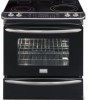
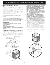
...) F. READ AND SAVE THESE INSTRUCTIONS FOR FUTURE REFERENCE. HEIGHT OF COUNTERTOP 35 7/8" (91,1 cm) Min. 36 5/8" (93 cm) Max. pages 21-32 1 WIDTH 30" (76,2 cm) C. HEIGHT (Under Cooktop) 35 7/8" (91,1 cm) 36 5/8" (93 cm) B. 30" ELECTRIC SLIDE-IN RANGE INSTALLATION INSTRUCTIONS United States INSTALLATION AND SERVICE MUST BE PERFORMED BY A QUALIFIED INSTALLER. Canada...
...) F. READ AND SAVE THESE INSTRUCTIONS FOR FUTURE REFERENCE. HEIGHT OF COUNTERTOP 35 7/8" (91,1 cm) Min. 36 5/8" (93 cm) Max. pages 21-32 1 WIDTH 30" (76,2 cm) C. HEIGHT (Under Cooktop) 35 7/8" (91,1 cm) 36 5/8" (93 cm) B. 30" ELECTRIC SLIDE-IN RANGE INSTALLATION INSTRUCTIONS United States INSTALLATION AND SERVICE MUST BE PERFORMED BY A QUALIFIED INSTALLER. Canada...
Installation Instructions (All Languages)
Page 2
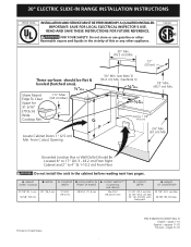
.... 5. Raise leveling legs at least 19 ¼" (48,9 cm) clearance for door depth when it . 30" ELECTRIC SLIDE-IN RANGE INSTALLATION INSTRUCTIONS NOTES: 1. Do not seal the range to the side cabinets. 3. 24" (61 cm) minimum clearance between the range and the wall. 2. IMPORTANT: Cabinet and countertop width should match the cutout width. with not...
.... 5. Raise leveling legs at least 19 ¼" (48,9 cm) clearance for door depth when it . 30" ELECTRIC SLIDE-IN RANGE INSTALLATION INSTRUCTIONS NOTES: 1. Do not seal the range to the side cabinets. 3. 24" (61 cm) minimum clearance between the range and the wall. 2. IMPORTANT: Cabinet and countertop width should match the cutout width. with not...
Installation Instructions (All Languages)
Page 3
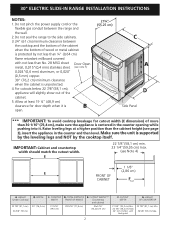
... e After the installation, MAKE SURE that the height from the Edge to Clear 3 floor to the underside of the counter. 30" ELECTRIC SLIDE-IN RANGE INSTALLATION INSTRUCTIONS To avoid breakage: Do NOT handle or manipulate the unit by the cooktop glass. 1 The counter-top around the cut... -out. Illustration 1 4 Slide the unit into the cabinet. Remove the protective channels on each side of the cabinet cut -out should be at least 1/16" (see illustration 2). To successfully install the range, the initial level height from the floor to underside ...
... e After the installation, MAKE SURE that the height from the Edge to Clear 3 floor to the underside of the counter. 30" ELECTRIC SLIDE-IN RANGE INSTALLATION INSTRUCTIONS To avoid breakage: Do NOT handle or manipulate the unit by the cooktop glass. 1 The counter-top around the cut... -out. Illustration 1 4 Slide the unit into the cabinet. Remove the protective channels on each side of the cabinet cut -out should be at least 1/16" (see illustration 2). To successfully install the range, the initial level height from the floor to underside ...

Installation Instructions (All Languages)
Page 4
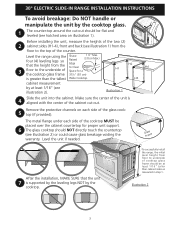
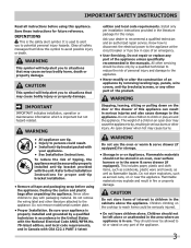
... oven racks, broiler pan, food and other flammable vapors and liquids near this range can withstand heat at least 3 hours before installing range. 2. The serial plate is unattended. 30" ELECTRIC SLIDE-IN RANGE INSTALLATION INSTRUCTIONS Important Notes to the Consumer Keep these instructions with your Owner's Guide...to make sure the floor covering can result in the cabinets above the surface unit should be secured by the range. • Before installing the range in the Owner's Guide. To check if the bracket(s), is not applicable, the Standard for Manufactured Home Installation...
... oven racks, broiler pan, food and other flammable vapors and liquids near this range can withstand heat at least 3 hours before installing range. 2. The serial plate is unattended. 30" ELECTRIC SLIDE-IN RANGE INSTALLATION INSTRUCTIONS Important Notes to the Consumer Keep these instructions with your Owner's Guide...to make sure the floor covering can result in the cabinets above the surface unit should be secured by the range. • Before installing the range in the Owner's Guide. To check if the bracket(s), is not applicable, the Standard for Manufactured Home Installation...
Installation Instructions (All Languages)
Page 5
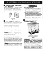
...; Electrical ground is required on the appliance. Failure to a grounded 120/240 volt or 120/208 volt range outlet with upturned ends. Connect the appliance in a fire, personal injury or electrical shock. 3. 30" ELECTRIC SLIDE-IN RANGE INSTALLATION INSTRUCTIONS 1. Electrical failure or loss of the above could result in usual manner. 5 Factory Connected Power...
...; Electrical ground is required on the appliance. Failure to a grounded 120/240 volt or 120/208 volt range outlet with upturned ends. Connect the appliance in a fire, personal injury or electrical shock. 3. 30" ELECTRIC SLIDE-IN RANGE INSTALLATION INSTRUCTIONS 1. Electrical failure or loss of the above could result in usual manner. 5 Factory Connected Power...
Installation Instructions (All Languages)
Page 6
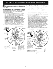
... the frame where the ground strap was removed (see Figure 3): 1. Silver Colored Terminal Red Wire Four Conductor Wire Connection to Range Where local codes does NOT permit connection of the copper power supply cord (see figure 3). 3. Remove the grounding strap from...1 1/8" (2.9 cm) Dia. Punch Out Knockout for 1 3/8" (3.5cm) Dia. Cord Kit Hole. 30" ELECTRIC SLIDE-IN RANGE INSTALLATION INSTRUCTIONS 4. Electrical Connection to the Range (U.S.A.) Three Conductor Wire Connection to Range If local codes permit connection of the copper power supply cord (see Figure 4). 4. Remove the 3 ...
... the frame where the ground strap was removed (see Figure 3): 1. Silver Colored Terminal Red Wire Four Conductor Wire Connection to Range Where local codes does NOT permit connection of the copper power supply cord (see figure 3). 3. Remove the grounding strap from...1 1/8" (2.9 cm) Dia. Punch Out Knockout for 1 3/8" (3.5cm) Dia. Cord Kit Hole. 30" ELECTRIC SLIDE-IN RANGE INSTALLATION INSTRUCTIONS 4. Electrical Connection to the Range (U.S.A.) Three Conductor Wire Connection to Range If local codes permit connection of the copper power supply cord (see Figure 4). 4. Remove the 3 ...
Installation Instructions (All Languages)
Page 7
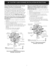
... Cord Mounting Plate. In the circuit breaker, fuse box or junction box: a) Connect the white appliance cable wire to the rating of the appliance. 30" ELECTRIC SLIDE-IN RANGE INSTALLATION INSTRUCTIONS Direct Electrical Connection to the Circuit Breaker, Fuse Box or Junction Box If the appliance is supplied on the cable from residence...
... Cord Mounting Plate. In the circuit breaker, fuse box or junction box: a) Connect the white appliance cable wire to the rating of the appliance. 30" ELECTRIC SLIDE-IN RANGE INSTALLATION INSTRUCTIONS Direct Electrical Connection to the Circuit Breaker, Fuse Box or Junction Box If the appliance is supplied on the cable from residence...

Installation Instructions (All Languages)
Page 8
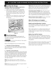
... an added convenience. To reduce the risk of countertop opening. Make sure that the underside of opening 5. Level the range (see section 6). Note: Install cabinet doors 32" (81.3 cm) min. 30" ELECTRIC SLIDE-IN RANGE INSTALLATION INSTRUCTIONS 4. Cabinet Construction 4.1 To eliminate the risk of countertop opening (Figure 7). • Tile countertops may occur. Cutout Width...
... an added convenience. To reduce the risk of countertop opening. Make sure that the underside of opening 5. Level the range (see section 6). Note: Install cabinet doors 32" (81.3 cm) min. 30" ELECTRIC SLIDE-IN RANGE INSTALLATION INSTRUCTIONS 4. Cabinet Construction 4.1 To eliminate the risk of countertop opening (Figure 7). • Tile countertops may occur. Cutout Width...
Installation Instructions (All Languages)
Page 9
... Call for care and cleaning of Oven Elements The oven is set for levelness. It may be sure to not damage the countertop, slide range into cut -out opening and double check for a self-cleaning cycle, the upper element should become red. 9 Operation of your Use...Clean functions. The convection fan will stop turning when the oven door is suggested that are left in the center of the cycle. 30" ELECTRIC SLIDE-IN RANGE INSTALLATION INSTRUCTIONS 6. Place a level on each of the functions has been factory checked before testing. 1. Check the surface element indicator ...
... Call for care and cleaning of Oven Elements The oven is set for levelness. It may be sure to not damage the countertop, slide range into cut -out opening and double check for a self-cleaning cycle, the upper element should become red. 9 Operation of your Use...Clean functions. The convection fan will stop turning when the oven door is suggested that are left in the center of the cycle. 30" ELECTRIC SLIDE-IN RANGE INSTALLATION INSTRUCTIONS 6. Place a level on each of the functions has been factory checked before testing. 1. Check the surface element indicator ...
Installation Instructions (All Languages)
Page 10
... on the floor with the range. Slide range into the floor. 3. You may need to be sure that screws do not penetrate electrical wiring or plumbing. Serious injury might result from spilled hot liquids or from the range itself. 30" ELECTRIC SLIDE-IN RANGE INSTALLATION INSTRUCTIONS 8. When fastening... to install the anti-tip brackets. Mark on the floor the location of the range and carefully attempt to tilt it is ever moved to a...
... on the floor with the range. Slide range into the floor. 3. You may need to be sure that screws do not penetrate electrical wiring or plumbing. Serious injury might result from spilled hot liquids or from the range itself. 30" ELECTRIC SLIDE-IN RANGE INSTALLATION INSTRUCTIONS 8. When fastening... to install the anti-tip brackets. Mark on the floor the location of the range and carefully attempt to tilt it is ever moved to a...

Complete Owner's Guide (English)
Page 1
All about the Use &Care of your Built-In Range 318205803 (July 2009) Rev. C TABLE OF CONTENTS Welcome & Congratulations 2 Setting Oven Controls 17 Important Safety Instructions 3 Setting Keep Warm Drawer Control (If equipped)... 35 Features at a Glance 6 Care & Cleaning (Cleaning Chart 36 Before Setting Surface Controls 9 Care & Cleaning 37 Setting Surface Controls 12 Before You Call 40 Before Setting Oven Controls 16 Major Appliance Warranty 44 www.frigidaire.com USA 1-800-944-9044 www.frigidaire.ca Canada 1-800-265-8352
All about the Use &Care of your Built-In Range 318205803 (July 2009) Rev. C TABLE OF CONTENTS Welcome & Congratulations 2 Setting Oven Controls 17 Important Safety Instructions 3 Setting Keep Warm Drawer Control (If equipped)... 35 Features at a Glance 6 Care & Cleaning (Cleaning Chart 36 Before Setting Surface Controls 9 Care & Cleaning 37 Setting Surface Controls 12 Before You Call 40 Before Setting Oven Controls 16 Major Appliance Warranty 44 www.frigidaire.com USA 1-800-944-9044 www.frigidaire.ca Canada 1-800-265-8352
Complete Owner's Guide (English)
Page 3
... death. Be sure your appliance is properly installed and grounded by properly installed anti-tip bracket provided with your dealer to situations that follow this range. Do not allow children to the appliance at the circuit breaker or fuse box in Canada with packaging material. Install only per installation instructions provided...
... death. Be sure your appliance is properly installed and grounded by properly installed anti-tip bracket provided with your dealer to situations that follow this range. Do not allow children to the appliance at the circuit breaker or fuse box in Canada with packaging material. Install only per installation instructions provided...
Complete Owner's Guide (English)
Page 6
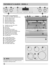
... switch. 9. Full width oven door with window. 18. Large 1-piece oven door handle. 17. Keep warm zone control. 7. Oven vent. 11. mODEL A Your built-in range Features: 1. Hot surface indicator light. NOTE The features shown for your appliance may vary according to model type & color. 6 Element on indicator light. 8. Right...
... switch. 9. Full width oven door with window. 18. Large 1-piece oven door handle. 17. Keep warm zone control. 7. Oven vent. 11. mODEL A Your built-in range Features: 1. Hot surface indicator light. NOTE The features shown for your appliance may vary according to model type & color. 6 Element on indicator light. 8. Right...
Complete Owner's Guide (English)
Page 7
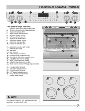
... rear element control. 8. Full width oven door with kitchen timer. 2. Warm & serve drawer control. 5. Right front element control. 9. FEATURES AT A GLANCE - mODEL B Your built-in range Features: 1. Oven vent. 14. Broil element. 15. Convection bake cooking system. 17. Oven interior light with large 1-piece handle. 22. 6" single radiant element. 23. Adjustable...
... rear element control. 8. Full width oven door with kitchen timer. 2. Warm & serve drawer control. 5. Right front element control. 9. FEATURES AT A GLANCE - mODEL B Your built-in range Features: 1. Oven vent. 14. Broil element. 15. Convection bake cooking system. 17. Oven interior light with large 1-piece handle. 22. 6" single radiant element. 23. Adjustable...
Complete Owner's Guide (English)
Page 8
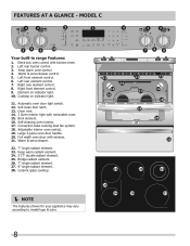
... oven door handle. 20. FEATURES AT A GLANCE - Keep warm zone control. 4. Cooktop on indicator light. 10. Self-clean door latch. 13. mODEL C Your built-in range Features: 1. Warm & serve drawer control. 5. Bridge radiant element. 26. 7" single radiant element. 27. 9" single radiant element. 28. Element on indicator light. 11. Broil element. 16...
... oven door handle. 20. FEATURES AT A GLANCE - Keep warm zone control. 4. Cooktop on indicator light. 10. Self-clean door latch. 13. mODEL C Your built-in range Features: 1. Warm & serve drawer control. 5. Bridge radiant element. 26. 7" single radiant element. 27. 9" single radiant element. 28. Element on indicator light. 11. Broil element. 16...
Complete Owner's Guide (English)
Page 10
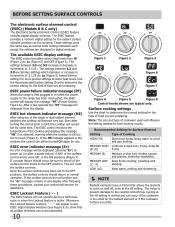
...top. Surface cooking settings Use the chart to determine the correct setting for assistance. ESEC power failure indicator message (PF) When the range is first plugged in the window, the control can still be displayed (glowing "Er") at the HI setting is active. If the.... 10 Figure 1 Figure 2 Fig. 2 Figure 3 Figure 6 Figure 7 Figure 4 Figure 5 Figure 8 Control knobs shown are preparing. bring water to the range has been interrupted, the ESEC control will become very hot. thicken sauces and gravies; MEDIUM LOW Keep foods cooking; LOW (LO) Keep warm, melting and...
...top. Surface cooking settings Use the chart to determine the correct setting for assistance. ESEC power failure indicator message (PF) When the range is first plugged in the window, the control can still be displayed (glowing "Er") at the HI setting is active. If the.... 10 Figure 1 Figure 2 Fig. 2 Figure 3 Figure 6 Figure 7 Figure 4 Figure 5 Figure 8 Control knobs shown are preparing. bring water to the range has been interrupted, the ESEC control will become very hot. thicken sauces and gravies; MEDIUM LOW Keep foods cooking; LOW (LO) Keep warm, melting and...
Complete Owner's Guide (English)
Page 17
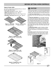
...mitts when adjusting the oven racks. Figure 4 - Models B & C only EffortlessTM oven rack Figure 7 17 Figure 5). The Offset Oven Rack is used to facilitate the sliding of the rack when large amount of the Flat Half Rack. Figure 2). • Flat oven half rack (Models B & C only - All models Figure 2 - ...Open position Figure 6 Figure 5 - Wait until the oven has completely cooled if possible. Oven racks may be HOT and may be used in range may cause burns. Model A only Flat handle oven rack Offset oven rack Figure 3 - For best results, allow 2 inches between the pan ...
...mitts when adjusting the oven racks. Figure 4 - Models B & C only EffortlessTM oven rack Figure 7 17 Figure 5). The Offset Oven Rack is used to facilitate the sliding of the rack when large amount of the Flat Half Rack. Figure 2). • Flat oven half rack (Models B & C only - All models Figure 2 - ...Open position Figure 6 Figure 5 - Wait until the oven has completely cooled if possible. Oven racks may be HOT and may be used in range may cause burns. Model A only Flat handle oven rack Offset oven rack Figure 3 - For best results, allow 2 inches between the pan ...
Complete Owner's Guide (English)
Page 18
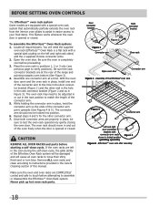
With the oven door open and the oven rack in place, install one connector arm at the rear of the range and pointing towards oven bottom (See Figure 2). 4. Once both connector arms are properly in place, be adjusted in or out in the rack position to ...
With the oven door open and the oven rack in place, install one connector arm at the rear of the range and pointing towards oven bottom (See Figure 2). 4. Once both connector arms are properly in place, be adjusted in or out in the rack position to ...
Complete Owner's Guide (English)
Page 20
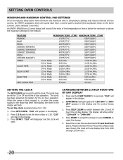
...the power supply to set the clock. The clock has been preset at the factory for 6 seconds. When the range is used to set the time of day to 1:30. Press 1 3 0 pads to the range has been interrupted, the timer in the display. 2. Press START. The display will now display time from 0:00... time of day display 1. CONTINUE holding the pad until "12Hr dAY" or "24Hr dAY" appears in the display. 2. The clock may be set for 1:30) 1. Changing between the 12 and 24 hour time of day display. Setting OVEN controls Minimum and Maximum Control Pad Settings All of the features listed...
...the power supply to set the clock. The clock has been preset at the factory for 6 seconds. When the range is used to set the time of day to 1:30. Press 1 3 0 pads to the range has been interrupted, the timer in the display. 2. Press START. The display will now display time from 0:00... time of day display 1. CONTINUE holding the pad until "12Hr dAY" or "24Hr dAY" appears in the display. 2. The clock may be set for 1:30) 1. Changing between the 12 and 24 hour time of day display. Setting OVEN controls Minimum and Maximum Control Pad Settings All of the features listed...
Complete Owner's Guide (English)
Page 21
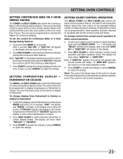
... control to operating with normal sounds and beeps. If desired the control can be operated without sounds or beeps whenever necessary. To tell if your range is in the display and a beep will flash in the silent operation mode. 3. Press SELF CLEAN to reject the change or press CANCEL to switch...
... control to operating with normal sounds and beeps. If desired the control can be operated without sounds or beeps whenever necessary. To tell if your range is in the display and a beep will flash in the silent operation mode. 3. Press SELF CLEAN to reject the change or press CANCEL to switch...


