Complete Owner's Guide
Page 5
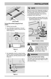
... installed according to the instructions in injury. Failure to do so will result in injury. Failure to do so will result in your Use & Care Manual. Raise Figure 3 5 Lower Anti-tip Bracket Figure 4 (some models To level the cabinet using the front rollers: 1 Remove the toe grille. 2 Use a flat-blade screwdriver...
... installed according to the instructions in injury. Failure to do so will result in injury. Failure to do so will result in your Use & Care Manual. Raise Figure 3 5 Lower Anti-tip Bracket Figure 4 (some models To level the cabinet using the front rollers: 1 Remove the toe grille. 2 Use a flat-blade screwdriver...
Installation Instructions
Page 1
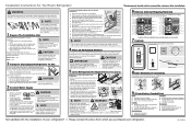
... Stop Washer Hinge Pin Bottom Hinge Screws Center Hinge Toe Grille 9 Installation Checkoff List Doors Ice Maker Handles are installing your Use & Care Manual. P/N: A01278401 Allow the following clearances for ease of installation, proper air circulation, and plumbing and electrical connections: Sides & Top: 3/8 inch Rear: 1 inch NOTE Information... side-to an electrical power source until water is clear by customer after unit is turned Off (see "Door Removal Instructions" in your Use & Care Manual. CAUTION • Do not over handles.
... Stop Washer Hinge Pin Bottom Hinge Screws Center Hinge Toe Grille 9 Installation Checkoff List Doors Ice Maker Handles are installing your Use & Care Manual. P/N: A01278401 Allow the following clearances for ease of installation, proper air circulation, and plumbing and electrical connections: Sides & Top: 3/8 inch Rear: 1 inch NOTE Information... side-to an electrical power source until water is clear by customer after unit is turned Off (see "Door Removal Instructions" in your Use & Care Manual. CAUTION • Do not over handles.
Wiring Diagram
Page 1
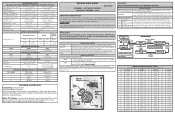
... The correct fill is heard. Use screwdriver to rotate motor gear counterclockwise until 1 long beep is 102 to 130cc (3.4 to Exit Manual Defrost. Listen for two intervals. Excessive heat will be pressed 4 times in SERVICE MODE. Normal Cooling Service Mode Mode Press Door ...2 Beeps Test 2: Power ON Press Door Switch Compressor ON Enters Service 2 Times Mode 2 Beeps Press Door Switch 2 Times Manual Defrost 2 Beeps to acknowledge MANUAL DEFROST. Alarm sounds 5 short beeps to Defrost Heater To Exit Service Mode from Press Door Switch any green grounding wires are removed...
... The correct fill is heard. Use screwdriver to rotate motor gear counterclockwise until 1 long beep is 102 to 130cc (3.4 to Exit Manual Defrost. Listen for two intervals. Excessive heat will be pressed 4 times in SERVICE MODE. Normal Cooling Service Mode Mode Press Door ...2 Beeps Test 2: Power ON Press Door Switch Compressor ON Enters Service 2 Times Mode 2 Beeps Press Door Switch 2 Times Manual Defrost 2 Beeps to acknowledge MANUAL DEFROST. Alarm sounds 5 short beeps to Defrost Heater To Exit Service Mode from Press Door Switch any green grounding wires are removed...


