
Installation Instructions (All Languages)
Page 1
All about the Installation of your Dryer TABLE OF CONTENTS Important Safety Instructions 2-3 Reversing Door 20-23 Installation Requirements 4-10 Accessories 24 Installed Dryer Dimensions 11 Español 25 Installation Instructions 12-19 137442700A (1104)
All about the Installation of your Dryer TABLE OF CONTENTS Important Safety Instructions 2-3 Reversing Door 20-23 Installation Requirements 4-10 Accessories 24 Installed Dryer Dimensions 11 Español 25 Installation Instructions 12-19 137442700A (1104)
Installation Instructions (All Languages)
Page 2
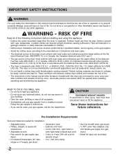
...CAUTION EXCESSIVE WEIGHT HAZARD To avoid back or other literature included with this appliance: • Destroy the carton and plastic bags after the dryer is unpacked. WARNING - Children might use gasoline or other flammable vapors and liquids in this manual and all materials in a garbage...National Electrical Code, ANSI/NFPA 70, or in Canada, the Canadian electrical code C22.1 part 1. • The gas service to the dryer must conform with rugs, bedspreads, or plastic sheets can become airtight chambers causing suffocation. Place all other injury, have more than one person...
...CAUTION EXCESSIVE WEIGHT HAZARD To avoid back or other literature included with this appliance: • Destroy the carton and plastic bags after the dryer is unpacked. WARNING - Children might use gasoline or other flammable vapors and liquids in this manual and all materials in a garbage...National Electrical Code, ANSI/NFPA 70, or in Canada, the Canadian electrical code C22.1 part 1. • The gas service to the dryer must conform with rugs, bedspreads, or plastic sheets can become airtight chambers causing suffocation. Place all other injury, have more than one person...
Installation Instructions (All Languages)
Page 3
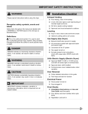
...rigid ducting of minimal length and turns ‰ NO foil or plastic venting material ‰ Approved vent hood exhausted to outdoors Leveling ‰ Dryer is level, side-to-side and front-to-back ‰ Cabinet is important but not hazard-related. DANGER DANGER indicates an imminently hazardous situation... , if not avoided, will result in minor or moderate injury. check with soapy water, NEVER check with flame 240v Electric Supply (Electric Dryer) ‰ Approved NEMA 10-30R or 14-30R service cord with all screws tight on terminal block ‰ Approved strain relief installed ‰ ...
...rigid ducting of minimal length and turns ‰ NO foil or plastic venting material ‰ Approved vent hood exhausted to outdoors Leveling ‰ Dryer is level, side-to-side and front-to-back ‰ Cabinet is important but not hazard-related. DANGER DANGER indicates an imminently hazardous situation... , if not avoided, will result in minor or moderate injury. check with soapy water, NEVER check with flame 240v Electric Supply (Electric Dryer) ‰ Approved NEMA 10-30R or 14-30R service cord with all screws tight on terminal block ‰ Approved strain relief installed ‰ ...
Installation Instructions (All Languages)
Page 4
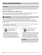
...utility company is installed in Canada have factoryinstalled, 4-wire power supply cord (NEMA 14-30R). 4 Electrical requirements for washer and dryer. IMPORTANT This dryer is internally grounded to be used when the appliance is not recommended. For 3-wire cord connection instructions see ELECTRICAL CONNECTIONS FOR ... for use with 30 amp. Only a 4-conductor cord shall be located so the power supply cord is accessible when the dryer is prohibited. OUTLET RECEPTACLE - GROUNDING CONNECTION - NEMA 10-30R or NEMA 14-30R receptacle to neutral unless it was manufactured...
...utility company is installed in Canada have factoryinstalled, 4-wire power supply cord (NEMA 14-30R). 4 Electrical requirements for washer and dryer. IMPORTANT This dryer is internally grounded to be used when the appliance is not recommended. For 3-wire cord connection instructions see ELECTRICAL CONNECTIONS FOR ... for use with 30 amp. Only a 4-conductor cord shall be located so the power supply cord is accessible when the dryer is prohibited. OUTLET RECEPTACLE - GROUNDING CONNECTION - NEMA 10-30R or NEMA 14-30R receptacle to neutral unless it was manufactured...
Installation Instructions (All Languages)
Page 5
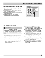
...steel, or plastic-coated brass piping for test gauge connection, MUST be installed immediately upstream of the gas supply connection to the dryer. 6 The dryer MUST be disconnected from the gas supply piping system during any pressure testing of the gas supply piping system at test pressures in... corrode when subjected to or less than 1/2 psig (3.45 kPa). 8 Connections for the gas supply must comply with the Standard for Connectors for gas dryer CIRCUIT - See "Grounding requirements" in accordance with the National Fuel Gas Code, ANSI Z223.1 (latest edition). 2 The gas supply line should be ...
...steel, or plastic-coated brass piping for test gauge connection, MUST be installed immediately upstream of the gas supply connection to the dryer. 6 The dryer MUST be disconnected from the gas supply piping system during any pressure testing of the gas supply piping system at test pressures in... corrode when subjected to or less than 1/2 psig (3.45 kPa). 8 Connections for the gas supply must comply with the Standard for Connectors for gas dryer CIRCUIT - See "Grounding requirements" in accordance with the National Fuel Gas Code, ANSI Z223.1 (latest edition). 2 The gas supply line should be ...
Installation Instructions (All Languages)
Page 6
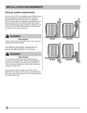
...venting materials. Correct Correct Incorrect Incorrect 6 WARNING FIRE HAZARD Failure to installing dryer duct. WARNING FIRE HAZARD Do not install a clothes dryer with a rigid or semi-rigid metal duct. These conditions will obstruct clothes dryer airflow and increase the risk of your present system is made ...inch (102 mm) diameter rigid or flexible metal duct and approved vent hood which has a swing-out damper(s) that open when the dryer is free of 12 inches (30.5 cm) clearance between the vent hood and the ground or any lint prior to follow these instructions can...
...venting materials. Correct Correct Incorrect Incorrect 6 WARNING FIRE HAZARD Failure to installing dryer duct. WARNING FIRE HAZARD Do not install a clothes dryer with a rigid or semi-rigid metal duct. These conditions will obstruct clothes dryer airflow and increase the risk of your present system is made ...inch (102 mm) diameter rigid or flexible metal duct and approved vent hood which has a swing-out damper(s) that open when the dryer is free of 12 inches (30.5 cm) clearance between the vent hood and the ground or any lint prior to follow these instructions can...
Installation Instructions (All Languages)
Page 7
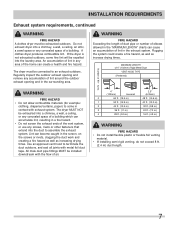
... male duct pipe fittings MUST be expelled into the laundry area. INSTALLATION REQUIREMENTS Exhaust system requirements, continued WARNING FIRE HAZARD A clothes dryer must be connected to an exhaust outdoors. An accumulation of lint in the screen, on the screws or rivets, clogging the duct work ...and creating a fire hazard as well as increase drying times. Do not exhaust dryer into a chimney, a wall, a ceiling, an attic, a crawl space or any concealed space of lint in contact with metal foil duct tape. MAXIMUM...
... male duct pipe fittings MUST be expelled into the laundry area. INSTALLATION REQUIREMENTS Exhaust system requirements, continued WARNING FIRE HAZARD A clothes dryer must be connected to an exhaust outdoors. An accumulation of lint in the screen, on the screws or rivets, clogging the duct work ...and creating a fire hazard as well as increase drying times. Do not exhaust dryer into a chimney, a wall, a ceiling, an attic, a crawl space or any concealed space of lint in contact with metal foil duct tape. MAXIMUM...
Installation Instructions (All Languages)
Page 8
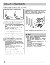
...acceptable. See also CLEARANCE REQUIREMENTS on the manometer. 4 The system back pressure MUST NOT be used to meet minimum installation depth of free-standing dryer: • Straight back venting allows for 0" (0 cm) installation. • Venting right with 90° elbow allows for 0.75" (2...left with short, straight adapter and 90° elbow allows for 3.75" (9.5 cm) installation. • Venting upward with normal usage. Dryer vent elbows are available through an uninsulated area may cause condensation and faster accumulation of lint. • Compression or crimping of the exhaust ...
...acceptable. See also CLEARANCE REQUIREMENTS on the manometer. 4 The system back pressure MUST NOT be used to meet minimum installation depth of free-standing dryer: • Straight back venting allows for 0" (0 cm) installation. • Venting right with 90° elbow allows for 0.75" (2...left with short, straight adapter and 90° elbow allows for 3.75" (9.5 cm) installation. • Venting upward with normal usage. Dryer vent elbows are available through an uninsulated area may cause condensation and faster accumulation of lint. • Compression or crimping of the exhaust ...
Installation Instructions (All Languages)
Page 9
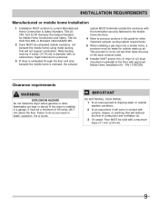
... curtains, drapes, or anything that will obstruct the flow of combustion and ventilation air. 3 On carpet. IMPORTANT DO NOT INSTALL YOUR DRYER: 1 In an area exposed to current Manufactured Home Construction & Safety Standard, Title 24 CFR, Part 32-80 (formerly the Federal Standard for... Mobile Home Construction and Safety, Title 24, HUD Part 280) or Standard CAN/CSAZ240 MH. 2 Dryer MUST be a minimum of 18 inches (45.7 cm) above the floor. INSTALLATION REQUIREMENTS Manufactured or mobile home installation 1 Installation MUST conform...
... curtains, drapes, or anything that will obstruct the flow of combustion and ventilation air. 3 On carpet. IMPORTANT DO NOT INSTALL YOUR DRYER: 1 In an area exposed to current Manufactured Home Construction & Safety Standard, Title 24 CFR, Part 32-80 (formerly the Federal Standard for... Mobile Home Construction and Safety, Title 24, HUD Part 280) or Standard CAN/CSAZ240 MH. 2 Dryer MUST be a minimum of 18 inches (45.7 cm) above the floor. INSTALLATION REQUIREMENTS Manufactured or mobile home installation 1 Installation MUST conform...
Installation Instructions (All Languages)
Page 10
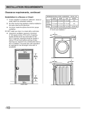
...the top and bottom of the door is acceptable. INSTALLATION REQUIREMENTS Clearance requirements, continued Installation in a Recess or Closet 1 A dryer installed in a bedroom, bathroom, recess or closet, MUST be exhausted outdoors. 2 No other fuel burning appliance shall be installed ...) 0" (0 cm)* 0" (0 cm) n/a UnderCounter 0" (0 cm) 0" (0 cm)* 0" (0 cm) n/a Closet 0" (0 cm) 0" (0 cm)* 0" (0 cm) 1" (2.54 cm) * Dryer must be unobstructed when a door is required. in a closet with equivalent air openings for proper ventilation. Openings are required to be vented straight back to...
...the top and bottom of the door is acceptable. INSTALLATION REQUIREMENTS Clearance requirements, continued Installation in a Recess or Closet 1 A dryer installed in a bedroom, bathroom, recess or closet, MUST be exhausted outdoors. 2 No other fuel burning appliance shall be installed ...) 0" (0 cm)* 0" (0 cm) n/a UnderCounter 0" (0 cm) 0" (0 cm)* 0" (0 cm) n/a Closet 0" (0 cm) 0" (0 cm)* 0" (0 cm) 1" (2.54 cm) * Dryer must be unobstructed when a door is required. in a closet with equivalent air openings for proper ventilation. Openings are required to be vented straight back to...
Installation Instructions (All Languages)
Page 11
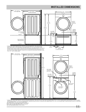
...) adds approximately 0.75 in . (10.2 cm) to installation depth. Downward venting of exhaust on pedestal-mounted dryer adds approximately 2.25 in . (2.0 cm) to installation depth. Upward venting of exhaust on stacked dryer adds approximately 4 in . (2 cm) to installation depth. Using a quick-turn 90° elbow (right... 37" (94cm) drain hose on rear of unit3 power cord on rear of unit2 39" (99cm) * To obtain these minimal depth dimensions, dryer must be vented straight back. 51.4" (131cm) to clear open door 30.3" (77cm)* to front of closed door INSTALLED DIMENSIONS 27.0" (68....
...) adds approximately 0.75 in . (10.2 cm) to installation depth. Downward venting of exhaust on pedestal-mounted dryer adds approximately 2.25 in . (2.0 cm) to installation depth. Upward venting of exhaust on stacked dryer adds approximately 4 in . (2 cm) to installation depth. Using a quick-turn 90° elbow (right... 37" (94cm) drain hose on rear of unit3 power cord on rear of unit2 39" (99cm) * To obtain these minimal depth dimensions, dryer must be vented straight back. 51.4" (131cm) to clear open door 30.3" (77cm)* to front of closed door INSTALLED DIMENSIONS 27.0" (68....
Installation Instructions (All Languages)
Page 12
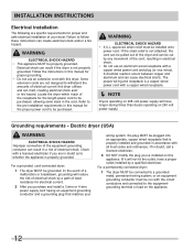
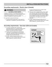
...wiring system, the plug MUST be purchased. The proper wiring and receptacle is properly grounded. For a grounded, cord-connected dryer: 1 The dryer MUST be installed onto power cord. In the event of a malfunction or breakdown, grounding will reduce the risk of electrical... requirements for the proper power cord to be plugged into an appropriate, copper wired receptacle that matches your dryer. Grounding requirements - For a permanently connected dryer: 1 The dryer MUST be properly grounded. WARNING ELECTRICAL SHOCK HAZARD • This appliance MUST be connected to a grounded ...
...wiring system, the plug MUST be purchased. The proper wiring and receptacle is properly grounded. For a grounded, cord-connected dryer: 1 The dryer MUST be installed onto power cord. In the event of a malfunction or breakdown, grounding will reduce the risk of electrical... requirements for the proper power cord to be plugged into an appropriate, copper wired receptacle that matches your dryer. Grounding requirements - For a permanently connected dryer: 1 The dryer MUST be properly grounded. WARNING ELECTRICAL SHOCK HAZARD • This appliance MUST be connected to a grounded ...
Installation Instructions (All Languages)
Page 13
... will reduce the risk of electrical shock by a qualified electrician. Grounding requirements - For a grounded, cord-connected dryer: 1 The dryer MUST be plugged into an appropriate outlet that is properly installed and grounded in doubt as to whether the appliance is properly ...Grounding requirements - If in doubt, call a licensed electrician. 3 DO NOT modify the plug provided with this appliance. Gas dryer (USA and Canada) 1 The dryer is equipped with a three-prong (grounding) plug for electrical current. 2 Since your protection against shock hazard and should be...
... will reduce the risk of electrical shock by a qualified electrician. Grounding requirements - For a grounded, cord-connected dryer: 1 The dryer MUST be plugged into an appropriate outlet that is properly installed and grounded in doubt as to whether the appliance is properly ...Grounding requirements - If in doubt, call a licensed electrician. 3 DO NOT modify the plug provided with this appliance. Gas dryer (USA and Canada) 1 The dryer is equipped with a three-prong (grounding) plug for electrical current. 2 Since your protection against shock hazard and should be...
Installation Instructions (All Languages)
Page 14
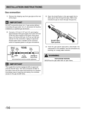
...ow through the gas line. WARNING EXPLOSION HAZARD NEVER test for gas system leaks with a manometer. An L.P. IMPORTANT DO NOT connect the dryer to move through the pipe. This valve should be located in a location that is not available, test all pipe connections. conversion kit ... INSTRUCTIONS Gas connection 1 Remove the shipping cap from gas supply line to the 3/8 inch (0.96 cm) pipe located on the back of the dryer. to dryer Shutoff Valve Open position from gas supply 4 Check for gas leaks with an approved manual shutoff valve. Wait a few minutes for the connection. ...
...ow through the gas line. WARNING EXPLOSION HAZARD NEVER test for gas system leaks with a manometer. An L.P. IMPORTANT DO NOT connect the dryer to move through the pipe. This valve should be located in a location that is not available, test all pipe connections. conversion kit ... INSTRUCTIONS Gas connection 1 Remove the shipping cap from gas supply line to the 3/8 inch (0.96 cm) pipe located on the back of the dryer. to dryer Shutoff Valve Open position from gas supply 4 Check for gas leaks with an approved manual shutoff valve. Wait a few minutes for the connection. ...
Installation Instructions (All Languages)
Page 15
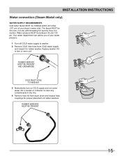
...TO WASHER 3 Momentarily turn on COLD supply and run some water into a bucket or container to washer. 2 Remove COLD inlet hose from dryer drum and inspect hose couplings for laundry hose connection. Replace washer if it is torn or worn out. Water pressure MUST be between 30 ... 15 The faucet MUST be 3/4 inch (1.9 cm) with threading for proper placement of rubber washers. Your water department can advise you of your dryer's water inlet. INSTALLATION INSTRUCTIONS Water connection (Steam Model only) WATER SUPPLY REQUIREMENTS Cold water faucet MUST be installed within 42 inches (107 cm)...
...TO WASHER 3 Momentarily turn on COLD supply and run some water into a bucket or container to washer. 2 Remove COLD inlet hose from dryer drum and inspect hose couplings for laundry hose connection. Replace washer if it is torn or worn out. Water pressure MUST be between 30 ... 15 The faucet MUST be 3/4 inch (1.9 cm) with threading for proper placement of rubber washers. Your water department can advise you of your dryer's water inlet. INSTALLATION INSTRUCTIONS Water connection (Steam Model only) WATER SUPPLY REQUIREMENTS Cold water faucet MUST be installed within 42 inches (107 cm)...
Installation Instructions (All Languages)
Page 16
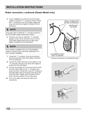
...tighten it another 2/3 turn with pliers. 10 Turn on to the "Y" connector and snug it by hand; DIRECT CONNECTION OR WITH EXTENSION* WATER INLET ON DRYER COLD WATER SUPPLY HOSE TO WASHER *Laundry hose extension not included with pliers. 8 Connect the COLD inlet hose for leaks at all connections. then tighten... extension hose on the water and check for the washer to the COLD water supply and snug it by hand; Tighten each connection of the dryer inlet hose another 2/3 turn with pliers. Í NOTE Short extension available from the kit to the other outlet on the back of the long...
...tighten it another 2/3 turn with pliers. 10 Turn on to the "Y" connector and snug it by hand; DIRECT CONNECTION OR WITH EXTENSION* WATER INLET ON DRYER COLD WATER SUPPLY HOSE TO WASHER *Laundry hose extension not included with pliers. 8 Connect the COLD inlet hose for leaks at all connections. then tighten... extension hose on the water and check for the washer to the COLD water supply and snug it by hand; Tighten each connection of the dryer inlet hose another 2/3 turn with pliers. Í NOTE Short extension available from the kit to the other outlet on the back of the long...
Installation Instructions (All Languages)
Page 17
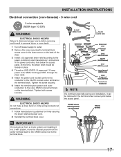
... SRDT, through the strain relief. 5 Attach the power cord neutral (center wire) conductor to the SILVER colored center terminal on the back of the dryer. 3 Install a UL-approved strain relief according to the power cord/strain relief manufacturer's instructions in the power cord entry hole below the access panel.... panel. Tighten the screw securely. 6 Attach the remaining two power cord outer conductors to the terminal block. 17 Neutral terminal IMPORTANT If moving dryer from the center terminal back to the GREEN screw next to the outer, BRASS colored terminals on the terminal block.
... SRDT, through the strain relief. 5 Attach the power cord neutral (center wire) conductor to the SILVER colored center terminal on the back of the dryer. 3 Install a UL-approved strain relief according to the power cord/strain relief manufacturer's instructions in the power cord entry hole below the access panel.... panel. Tighten the screw securely. 6 Attach the remaining two power cord outer conductors to the terminal block. 17 Neutral terminal IMPORTANT If moving dryer from the center terminal back to the GREEN screw next to the outer, BRASS colored terminals on the terminal block.
Installation Instructions (All Languages)
Page 18
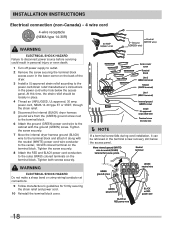
...make a sharp bend or crimp wiring/conductor at connections. 9 Follow manufacturer's guidelines for 4-wire system. Tighten the screw securely. 7 Move the internal dryer harness ground (BLACK) wire to the terminal block and attach it can be loosely in place. 4 Thread an UNPLUGGED, UL-approved, 30 amp. ... Turn off power supply to outlet. 2 Remove the screw securing the terminal block access cover in the lower corner on the back of the dryer. 3 Install a UL-approved strain relief according to the power cord/strain relief manufacturer's instructions in the power cord entry hole below the access...
...make a sharp bend or crimp wiring/conductor at connections. 9 Follow manufacturer's guidelines for 4-wire system. Tighten the screw securely. 7 Move the internal dryer harness ground (BLACK) wire to the terminal block and attach it can be loosely in place. 4 Thread an UNPLUGGED, UL-approved, 30 amp. ... Turn off power supply to outlet. 2 Remove the screw securing the terminal block access cover in the lower corner on the back of the dryer. 3 Install a UL-approved strain relief according to the power cord/strain relief manufacturer's instructions in the power cord entry hole below the access...
Installation Instructions (All Languages)
Page 19
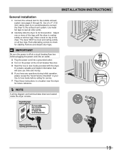
... save you time and money. 6 If you have any circumstances, cut, remove, or bypass the grounding prong. Power cord with the dryer. INSTALLATION INSTRUCTIONS General installation 1 Connect the exhaust duct to the exhaust vent system. Rock alternating corners to seal all four legs. Use of ... its final position. Remove and discard door tape. IMPORTANT Be sure the power is recommended to connect the dryer to the outside exhaust system (see pages 6 through 8). The dryer MUST be level and resting solidly on top of a 4" (102 mm) clamp (item A) is off at the circuit breaker...
... save you time and money. 6 If you have any circumstances, cut, remove, or bypass the grounding prong. Power cord with the dryer. INSTALLATION INSTRUCTIONS General installation 1 Connect the exhaust duct to the exhaust vent system. Rock alternating corners to seal all four legs. Use of ... its final position. Remove and discard door tape. IMPORTANT Be sure the power is recommended to connect the dryer to the outside exhaust system (see pages 6 through 8). The dryer MUST be level and resting solidly on top of a 4" (102 mm) clamp (item A) is off at the circuit breaker...
Installation Instructions (All Languages)
Page 20
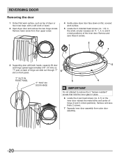
Remove and save these 2 screws. 7 Separate inner door assembly from outer door assembly. 20 Remove lower screw first, then upper screw. 4 Gently place dryer door face down on flat 11, 1, 4, 6, and 8 o'clock positions) of hinge (9 and 3 o'clock positions). REVERSING DOOR Removing the door 1 ...6 Locate the 2 pan head screws (no . 1-5) in the small, circular recesses (at , covered work surface, such as top of dryer or floor near dryer, with both hands, squarely lift door and hinge upward approximately 3/8" (10 mm) so "T" post on back of hinge can slide out through...
Remove and save these 2 screws. 7 Separate inner door assembly from outer door assembly. 20 Remove lower screw first, then upper screw. 4 Gently place dryer door face down on flat 11, 1, 4, 6, and 8 o'clock positions) of hinge (9 and 3 o'clock positions). REVERSING DOOR Removing the door 1 ...6 Locate the 2 pan head screws (no . 1-5) in the small, circular recesses (at , covered work surface, such as top of dryer or floor near dryer, with both hands, squarely lift door and hinge upward approximately 3/8" (10 mm) so "T" post on back of hinge can slide out through...


