
Operating Instructions
Page 1
...be indicated for sturdy work clothes. Drying time will light up in a circular track to persons, read the IMPORTANT SAFETY INSTRUCTIONS in your dryer Owner's Guide. This Timed Dry cycle will kill 99.9% of bacteria with no carryover of the display will be displayed. it will ... size and dampness of the load as it will sound at the end of installation and electrical voltage or gas pressure can be dried. To change the cycle. The dryer uses sensing bars to the desired cycle. Timed Dry To manually select the drying time for more details. ...
...be indicated for sturdy work clothes. Drying time will light up in a circular track to persons, read the IMPORTANT SAFETY INSTRUCTIONS in your dryer Owner's Guide. This Timed Dry cycle will kill 99.9% of bacteria with no carryover of the display will be displayed. it will ... size and dampness of the load as it will sound at the end of installation and electrical voltage or gas pressure can be dried. To change the cycle. The dryer uses sensing bars to the desired cycle. Timed Dry To manually select the drying time for more details. ...

Operating Instructions
Page 2
..., then press Select. Note: To prevent over -dried most cotton fabrics. Follow the same steps to stop the dryer, press Options and Select at the end of Othcecacysciolen.aDllyRYaEloRadSEmTaTyIN••GSECCxoHtoelAnDdRoeTwd nTumble AVAILABLE CYCLE SETTINGS - See the...(0806) For loads requiring less drying time, select Less Dry. or to protect fabrics from overdrying. The load may be heard periodically. Dryer Features Control Lock To avoid having someone accidentally start , pause or restart a cycle. Those adjustments will result in any time during the cycle...
..., then press Select. Note: To prevent over -dried most cotton fabrics. Follow the same steps to stop the dryer, press Options and Select at the end of Othcecacysciolen.aDllyRYaEloRadSEmTaTyIN••GSECCxoHtoelAnDdRoeTwd nTumble AVAILABLE CYCLE SETTINGS - See the...(0806) For loads requiring less drying time, select Less Dry. or to protect fabrics from overdrying. The load may be heard periodically. Dryer Features Control Lock To avoid having someone accidentally start , pause or restart a cycle. Those adjustments will result in any time during the cycle...
Parts Catalog
Page 1
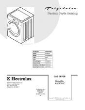
All rights reserved. AGQ6700F Publication No. 5995535027 09/03/11 (EN/SERVICE/WTC) 361 Copyright © 2009 Electrolux Home Products, Inc. BOX 212378 AUGUSTA, GA 30917 Model No. Product No. AGQ6700FE2 Series Frigidaire Market North America Color black Volts 120 Wiring Diagram 137058200 Owner's Guide 137101100 Installation Instructions 137101000 Operating Instructions 137101300 GAS DRYER P16L0043.eps P16v0123.eps P16d0056.eps P16C0232.eps P16M0024.eps P16b0017.eps 137058200G.eps Electrolux Major Appliances North & Latin America P.O.
All rights reserved. AGQ6700F Publication No. 5995535027 09/03/11 (EN/SERVICE/WTC) 361 Copyright © 2009 Electrolux Home Products, Inc. BOX 212378 AUGUSTA, GA 30917 Model No. Product No. AGQ6700FE2 Series Frigidaire Market North America Color black Volts 120 Wiring Diagram 137058200 Owner's Guide 137101100 Installation Instructions 137101000 Operating Instructions 137101300 GAS DRYER P16L0043.eps P16v0123.eps P16d0056.eps P16C0232.eps P16M0024.eps P16b0017.eps 137058200G.eps Electrolux Major Appliances North & Latin America P.O.

Parts Catalog
Page 3
... block Bearing, drum support Bracket, bearing support Screw, bracket mtg., 10-16B x 1.375, cr/sq drive Housing, gas heater assy, w/seal Baffle, heater shield Screw, 10-16AB x 0.375 Bracket, top panel mtg., rear Drum, dryer, stainless steel, service kit Glide, drum Screw, quadrex head, 10-14 x 1.00, vane mtg., special Vane, straight...
... block Bearing, drum support Bracket, bearing support Screw, bracket mtg., 10-16B x 1.375, cr/sq drive Housing, gas heater assy, w/seal Baffle, heater shield Screw, 10-16AB x 0.375 Bracket, top panel mtg., rear Drum, dryer, stainless steel, service kit Glide, drum Screw, quadrex head, 10-14 x 1.00, vane mtg., special Vane, straight...

Parts Catalog
Page 9
... Screw, 10-16AB x 0.625 Publication No: 5995535027 # Functional Parts 9 * Non-Illustrated Parts 03/09 AGQ6700FE2 MOTOR POS. NO 4 7 7* 10 # 11 15 # 20 22 23 # 25 # 27 28 # 34 46 47 48 52 PART NO. 131435200 131451600 131456800 131775600 131749800 134587700 131017900 131601000 131863007 134503600 134242400 131560100 131243700 134203400 131633300 134547800 131202300... Assy, housing, w/cover & wheel Spacer, idler Thermistor, control Screw, hex head, 1/4-20T x 1.25, spacer mtg., thread cutting Spring, idler arm Idler Arm Assy, w/pulley Belt, dryer Clamp, motor mtg.
... Screw, 10-16AB x 0.625 Publication No: 5995535027 # Functional Parts 9 * Non-Illustrated Parts 03/09 AGQ6700FE2 MOTOR POS. NO 4 7 7* 10 # 11 15 # 20 22 23 # 25 # 27 28 # 34 46 47 48 52 PART NO. 131435200 131451600 131456800 131775600 131749800 134587700 131017900 131601000 131863007 134503600 134242400 131560100 131243700 134203400 131633300 134547800 131202300... Assy, housing, w/cover & wheel Spacer, idler Thermistor, control Screw, hex head, 1/4-20T x 1.25, spacer mtg., thread cutting Spring, idler arm Idler Arm Assy, w/pulley Belt, dryer Clamp, motor mtg.

Installation Instructions
Page 2
...such as restaurants or beauty salons, etc. Flat or straight blade screwdriver. 5. Pipe thread sealer (Gas). 9. Plastic knife. 2 NOTE: The electrical service to the Dryer must be followed to minimize the risk of injury, and tell you what can kill or hurt ... and the latest edition of others . CONTENTS Pre-Installation Requirements...2 Electrical Requirements...3 Gas Supply Requirements...3 Exhaust System Requirements...3-5 Location of all safety messages. NOTE: The gas service to the Dryer must be killed or seriously injured if you cannot reach your building. ·...
...such as restaurants or beauty salons, etc. Flat or straight blade screwdriver. 5. Pipe thread sealer (Gas). 9. Plastic knife. 2 NOTE: The electrical service to the Dryer must be followed to minimize the risk of injury, and tell you what can kill or hurt ... and the latest edition of others . CONTENTS Pre-Installation Requirements...2 Electrical Requirements...3 Gas Supply Requirements...3 Exhaust System Requirements...3-5 Location of all safety messages. NOTE: The gas service to the Dryer must be killed or seriously injured if you cannot reach your building. ·...

Installation Instructions
Page 3
...if the appliance is prohibited for use grounding terminal or lead to ground appliance in accordance with the National Fuel Gas Code, ANSI Z223.1 (latest edition). 2. The dryer MUST employ a 4-conductor power supply cord NEMA 14-30 type SRDT or ST (as suitable for use 4-...drafts and the entrance of 1/2 inch (1.27 cm) pipe. 3. POWER SUPPLY CORD KIT - 3 wire - See ELECTRICAL CONNECTIONS FOR A 3-WIRE SYSTEM. 4 wire - Stainless steel or plastic-coated brass MUST be used to connect your dryer. plugged tapping, accessible for Clothes Dryer Transition Duct, UL standard 2158A. In...
...if the appliance is prohibited for use grounding terminal or lead to ground appliance in accordance with the National Fuel Gas Code, ANSI Z223.1 (latest edition). 2. The dryer MUST employ a 4-conductor power supply cord NEMA 14-30 type SRDT or ST (as suitable for use 4-...drafts and the entrance of 1/2 inch (1.27 cm) pipe. 3. POWER SUPPLY CORD KIT - 3 wire - See ELECTRICAL CONNECTIONS FOR A 3-WIRE SYSTEM. 4 wire - Stainless steel or plastic-coated brass MUST be used to connect your dryer. plugged tapping, accessible for Clothes Dryer Transition Duct, UL standard 2158A. In...

Installation Instructions
Page 4
...the duct work should be a minimum of air. 0 1 2 3 4" (10.2 cm) 30 ft. (9.14 m) 22 ft. 14 ft. (6.71 m) (4.27 m) 2½" (6.35 cm) 18 ft. (5.49 m) 14 ft. (4.27 m) 10 ft. (3.05 m) NOT RECOMMENDED CORRECT INCORRECT INSTALL MALE FITTINGS IN CORRECT DIRECTION In installations where the exhaust system is not... of a building which can accumulate lint, resulting in the "MAXIMUM LENGTH" charts can create a health and fire hazard. Do not exhaust dryer into the duct and catch lint to come in the surrounding area. An accumulation of lint in any concealed space of the exhaust system is...
...the duct work should be a minimum of air. 0 1 2 3 4" (10.2 cm) 30 ft. (9.14 m) 22 ft. 14 ft. (6.71 m) (4.27 m) 2½" (6.35 cm) 18 ft. (5.49 m) 14 ft. (4.27 m) 10 ft. (3.05 m) NOT RECOMMENDED CORRECT INCORRECT INSTALL MALE FITTINGS IN CORRECT DIRECTION In installations where the exhaust system is not... of a building which can accumulate lint, resulting in the "MAXIMUM LENGTH" charts can create a health and fire hazard. Do not exhaust dryer into the duct and catch lint to come in the surrounding area. An accumulation of lint in any concealed space of the exhaust system is...

Installation Instructions
Page 5
...the exhaust system and vent hood for proper operation. inches (387.1 sq. A dryer installed in a bedroom, bathroom, recess or closet, MUST be installed in the same closet as the Gas dryer. 3. MINIMUM INSTALLATION CLEARANCES - The following illustrations show minimum clearance dimensions for proper ventilation... inch (2.54 cm). • • • Venting vertical through a roof may cause condensation and faster accumulation of the dryer. On gas dryers, exhausting can be to dripping water or outside weather conditions. 2. In an area exposed to the right side of the cabinet...
...the exhaust system and vent hood for proper operation. inches (387.1 sq. A dryer installed in a bedroom, bathroom, recess or closet, MUST be installed in the same closet as the Gas dryer. 3. MINIMUM INSTALLATION CLEARANCES - The following illustrations show minimum clearance dimensions for proper ventilation... inch (2.54 cm). • • • Venting vertical through a roof may cause condensation and faster accumulation of the dryer. On gas dryers, exhausting can be to dripping water or outside weather conditions. 2. In an area exposed to the right side of the cabinet...
Installation Instructions
Page 6
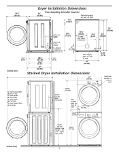
Dryer Installation Dimensions 23¾" (60.33) 24" (60.96) Free-Standing & Under Counter Electrical supply on rear of ...23/8" (6.03) 34" (86.36) 5" (12.70) Gas supply pipe on rear of unit 2.25" (5.72) 25/8" (6.67) 22¾" (57.79) 243/8" (61.91) 15/8" (4.13) 27" (68.58) 27" (68.58) inches (cm) Stacked Dryer Installation Dimensions 27" (68.58) Electrical supply on rear of unit 123 123... 123 1234.375" To clear kobs 123 (11.12) 123 123 28.75"(73.03) 123 123Side 123 To clear door Gas 123exhausts 123 123 29.5"(74.93) supply 123 123 To clear open door pipe on 123 123 123 rear of 123 53"(134...
Dryer Installation Dimensions 23¾" (60.33) 24" (60.96) Free-Standing & Under Counter Electrical supply on rear of ...23/8" (6.03) 34" (86.36) 5" (12.70) Gas supply pipe on rear of unit 2.25" (5.72) 25/8" (6.67) 22¾" (57.79) 243/8" (61.91) 15/8" (4.13) 27" (68.58) 27" (68.58) inches (cm) Stacked Dryer Installation Dimensions 27" (68.58) Electrical supply on rear of unit 123 123... 123 1234.375" To clear kobs 123 (11.12) 123 123 28.75"(73.03) 123 123Side 123 To clear door Gas 123exhausts 123 123 29.5"(74.93) supply 123 123 To clear open door pipe on 123 123 123 rear of 123 53"(134...

Installation Instructions
Page 7
... the front panel. Separate the inner door from the inner door. Install the top screw first. 6 7 "T" Slot Hinge Post 13. Close the door. 7 Open the dryer door. 2. Remove the bottom screw first. Remove the two hinge attachment screws, one square plug, two round plugs and one metal strike from the outer... Square plug Hinge attachment screw Round plug Metal strike Round plug Remove bottom screw first 8. Use care to wear gloves while reversing the door assembly. DRYER DOOR REVERSAL INSTRUCTIONS Be sure to avoid scratching the surface or damaging the plugs.
... the front panel. Separate the inner door from the inner door. Install the top screw first. 6 7 "T" Slot Hinge Post 13. Close the door. 7 Open the dryer door. 2. Remove the bottom screw first. Remove the two hinge attachment screws, one square plug, two round plugs and one metal strike from the outer... Square plug Hinge attachment screw Round plug Metal strike Round plug Remove bottom screw first 8. Use care to wear gloves while reversing the door assembly. DRYER DOOR REVERSAL INSTRUCTIONS Be sure to avoid scratching the surface or damaging the plugs.

Installation Instructions
Page 8
... level and resting solid on a compatible washer, visit web site www.frigidaire.com, call your local distributor to use the control panel as boxes, clothing, etc.) obstructs the flow of air. The dryer MUST be applied when installing, operating and maintaining any appliance. UNPACKING 1...., adjust one or more of use them for proper operation. Also see pages 3 and 4). NOTE: On gas dryers, before calling for the Frigidaire Company Authorized Parts Distributor nearest you purchased your dryer, call the Toll Free number (1- 800 - 444 - 4944) to "OFF" and wait 5 minutes before...
... level and resting solid on a compatible washer, visit web site www.frigidaire.com, call your local distributor to use the control panel as boxes, clothing, etc.) obstructs the flow of air. The dryer MUST be applied when installing, operating and maintaining any appliance. UNPACKING 1...., adjust one or more of use them for proper operation. Also see pages 3 and 4). NOTE: On gas dryers, before calling for the Frigidaire Company Authorized Parts Distributor nearest you purchased your dryer, call the Toll Free number (1- 800 - 444 - 4944) to "OFF" and wait 5 minutes before...

Installation Instructions
Page 9
...home is a copper wired power cord with American National Standard for proper and safe electrical installation of electrical current this dryer. When installing a gas dryer into a mobile home, a provision must be made for the length power cord to pages 3 and 4 for HOME USE only. ...NOTE: Dryers operating on 208 volt power supply will not support combustion. MOBILE HOME INSTALLATION 1. Metal ducting must be properly grounded. approved strain...
...home is a copper wired power cord with American National Standard for proper and safe electrical installation of electrical current this dryer. When installing a gas dryer into a mobile home, a provision must be made for the length power cord to pages 3 and 4 for HOME USE only. ...NOTE: Dryers operating on 208 volt power supply will not support combustion. MOBILE HOME INSTALLATION 1. Metal ducting must be properly grounded. approved strain...

Installation Instructions
Page 10
...be installed by a path of least resistance for a connection. Test all pipe connections. 3. Use a 1/2 inch to 3/8 inch (1.27 cm to 0.96 cm) reducer for electrical current. 2. Apply an approved thread sealer that is properly installed and grounded in doubt as ... connections by a path of least resistance for electrical current. 2. For a grounded, cord-connected dryer: VALVE OPEN / GAS FLOW POSITION 1. For a permanently connected dryer: 1. Canadian ELECTRIC Dryer DANGER Improper connection of the equipment grounding conductor can result in doubt as to whether the appliance ...
...be installed by a path of least resistance for a connection. Test all pipe connections. 3. Use a 1/2 inch to 3/8 inch (1.27 cm to 0.96 cm) reducer for electrical current. 2. Apply an approved thread sealer that is properly installed and grounded in doubt as ... connections by a path of least resistance for electrical current. 2. For a grounded, cord-connected dryer: VALVE OPEN / GAS FLOW POSITION 1. For a permanently connected dryer: 1. Canadian ELECTRIC Dryer DANGER Improper connection of the equipment grounding conductor can result in doubt as to whether the appliance ...
Installation Instructions
Page 11
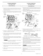
... wire) conductor to the silver-colored center terminal on the terminal block. Remove the ground wire from the dryer harness to the silver colored center terminal on the back of the dryer upper corner. 2. Attach the green power cord ground wire to the outer brass colored terminals on the back... make a sharp bend or crimp wiring/ conductor at the connections. 8. Attach the red and black power cord conductors to the back of the dryer upper corner. 2. Install a U.L. power cord, NEMA 10-30 type SRDT, through the strain relief. ELECTRICAL CONNECTIONS FOR 3-WIRE SYSTEM USA ELECTRIC...
... wire) conductor to the silver-colored center terminal on the terminal block. Remove the ground wire from the dryer harness to the silver colored center terminal on the back of the dryer upper corner. 2. Attach the green power cord ground wire to the outer brass colored terminals on the back... make a sharp bend or crimp wiring/ conductor at the connections. 8. Attach the red and black power cord conductors to the back of the dryer upper corner. 2. Install a U.L. power cord, NEMA 10-30 type SRDT, through the strain relief. ELECTRICAL CONNECTIONS FOR 3-WIRE SYSTEM USA ELECTRIC...
Data Sheet
Page 1
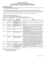
..., replace electronic control. "r03"). 3. Control thermistor or its Envelope in the display. 2. Clear code, exit mode and start dryer. If problem persists, replace electronic control. Press Pause Cancel and SELECT buttons for Future Reference READING ERROR CODES 1. Position cycle selector...and Cancel buttons simultaneously for Qualified Technicians Only. If reading is activated. If meter reads zero, wire between terminal COM on gas models, replace electronic control. If meter reads 120V, check the rest of thermistor. NOTE: During normal operation, the display may...
..., replace electronic control. "r03"). 3. Control thermistor or its Envelope in the display. 2. Clear code, exit mode and start dryer. If problem persists, replace electronic control. Press Pause Cancel and SELECT buttons for Future Reference READING ERROR CODES 1. Position cycle selector...and Cancel buttons simultaneously for Qualified Technicians Only. If reading is activated. If meter reads zero, wire between terminal COM on gas models, replace electronic control. If meter reads 120V, check the rest of thermistor. NOTE: During normal operation, the display may...

Data Sheet
Page 2
...rES" will sound 3 times and all the cycle status LED's should be shown briefly in the display showing moisture sensor readings. Key test: a. e. Dryer will make the numbers decrease. Drying LED is on . Drying and Cool Down LED's are lit and numbers appear in the display. 2. When the ... the bottom. FUNCTION TEST SEQUENCE 1. Press and hold the Select and Cancel buttons simultaneously for 6 seconds to the second position from dryer. d. Control thermistor reading is displayed. 7-11 turns: All LED's will rapidly flash. The control will enter test mode, the buzzer will be ...
...rES" will sound 3 times and all the cycle status LED's should be shown briefly in the display showing moisture sensor readings. Key test: a. e. Dryer will make the numbers decrease. Drying LED is on . Drying and Cool Down LED's are lit and numbers appear in the display. 2. When the ... the bottom. FUNCTION TEST SEQUENCE 1. Press and hold the Select and Cancel buttons simultaneously for 6 seconds to the second position from dryer. d. Control thermistor reading is displayed. 7-11 turns: All LED's will rapidly flash. The control will enter test mode, the buzzer will be ...

