Fluke 741B - 743B Users Manual
Page 10
...Tachometer...92 34. Calibrating a Pressure-to-Current (P/I /P) Transmitter 89 29. Limit Switch Terminology...74 25. LCD Operating Environment Specification 120 viii Connections for Simulating an RTD 56 22. Checking a Switch ...92 33. Checking a Vortex Sheeding Flowmeter 95 37. Measuring Voltage Drop ......87 27. 741B/743B Users Manual 18. Calibrating a mV to -Pressure (I ) Transmitter 93 35. Connections for Supplying Loop Power 49 19. Measuring ...
...Tachometer...92 34. Calibrating a Pressure-to-Current (P/I /P) Transmitter 89 29. Limit Switch Terminology...74 25. LCD Operating Environment Specification 120 viii Connections for Simulating an RTD 56 22. Checking a Switch ...92 33. Checking a Vortex Sheeding Flowmeter 95 37. Measuring Voltage Drop ......87 27. 741B/743B Users Manual 18. Calibrating a mV to -Pressure (I ) Transmitter 93 35. Connections for Supplying Loop Power 49 19. Measuring ...
Fluke 741B - 743B Users Manual
Page 12
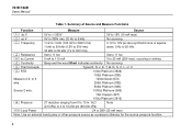
741B/743B Users Manual Table 1. H2O (2.5 kPa) to 0 to 10 in. Summary of Source and Measure Functions Function Measure Source v dc V 0V to +/-300V 0V to ... sinking q Continuity Beep and the word Short indicates continuity No sourcing t Thermocouple Types E, N, J, K, T, B, R, S, C, L, or U t RTD 100Ω Platinum (3926) 100Ω Platinum (385) Measure 2,3, or 4 120Ω Nickel (672) wire. 200Ω Platinum (385) 500Ω Platinum (385) Source 2 wire. 1000Ω Platinum (385) 10Ω Copper (427) 100Ω Platinum...
741B/743B Users Manual Table 1. H2O (2.5 kPa) to 0 to 10 in. Summary of Source and Measure Functions Function Measure Source v dc V 0V to +/-300V 0V to ... sinking q Continuity Beep and the word Short indicates continuity No sourcing t Thermocouple Types E, N, J, K, T, B, R, S, C, L, or U t RTD 100Ω Platinum (3926) 100Ω Platinum (385) Measure 2,3, or 4 120Ω Nickel (672) wire. 200Ω Platinum (385) 500Ω Platinum (385) Source 2 wire. 1000Ω Platinum (385) 10Ω Copper (427) 100Ω Platinum...

Fluke 741B - 743B Users Manual
Page 33
... Setup mode. Using the Optional Battery Eliminator Caution To avoid damage to the calibrator, use the optional Fluke Model BE9005 Battery Eliminator to highlight Off following Battery Save Timeout. The battery eliminator does not charge the...e or the Choices softkey. 4. The setting is Off. Where ac power is available, you can use only Fluke Model BE9005 Series Battery Eliminator, available from the calibrator. To accept the timeout period shown on the display, you ... the calibrator off the power. Enter your Fluke representative. Press s. 2. Press Done to 120 minutes). 9.
... Setup mode. Using the Optional Battery Eliminator Caution To avoid damage to the calibrator, use the optional Fluke Model BE9005 Battery Eliminator to highlight Off following Battery Save Timeout. The battery eliminator does not charge the...e or the Choices softkey. 4. The setting is Off. Where ac power is available, you can use only Fluke Model BE9005 Series Battery Eliminator, available from the calibrator. To accept the timeout period shown on the display, you ... the calibrator off the power. Enter your Fluke representative. Press s. 2. Press Done to 120 minutes). 9.

Fluke 741B - 743B Users Manual
Page 36
...Calibrator You can minimize battery usage by setting the calibrator to highlight Off following Backlight Timeout. 7. Press d to move the cursor to 120 minutes). 9. Enter your name or some other alphanumeric identifier into the calibrator to highlight the timeout period following Auto Backlight Off. 3. ...Press the Done softkey or s to load an identifier: 1. To automatically turn the display backlight off . Proceed as ID. 26 741B/743B Users Manual Using the Backlight Press C to highlight On, then press e. 5. When the backlight is on and Auto Backlight Off is on...
...Calibrator You can minimize battery usage by setting the calibrator to highlight Off following Backlight Timeout. 7. Press d to move the cursor to 120 minutes). 9. Enter your name or some other alphanumeric identifier into the calibrator to highlight the timeout period following Auto Backlight Off. 3. ...Press the Done softkey or s to load an identifier: 1. To automatically turn the display backlight off . Proceed as ID. 26 741B/743B Users Manual Using the Backlight Press C to highlight On, then press e. 5. When the backlight is on and Auto Backlight Off is on...

Fluke 741B - 743B Users Manual
Page 47
RTD Types Accepted RTD Type Ice Point (R ) 0 Pt100 (3926) 100Ω *Pt100 (385) 100Ω Ni120 (672) 120Ω Pt200 (385) 200Ω Pt500 (385) 500Ω Pt1000 (385) 1000Ω Cu10 (427) 9.035Ω ** Pt100 (3916) 100Ω *Per IEC 751-Standard **...
RTD Types Accepted RTD Type Ice Point (R ) 0 Pt100 (3926) 100Ω *Pt100 (385) 100Ω Ni120 (672) 120Ω Pt200 (385) 200Ω Pt500 (385) 500Ω Pt1000 (385) 1000Ω Cu10 (427) 9.035Ω ** Pt100 (3916) 100Ω *Per IEC 751-Standard **...

Fluke 741B - 743B Users Manual
Page 124
... Manual Temperature, Resistance Temperature Detectors Type (α) Temperature, RTDs, Model 741B and 743B Range °C Measure °C 1 Year 2 Year 100Ω Pt(3926) -200 to 0 0.3 0.4 0 to 630 0.5 0.8 100Ω Pt(385) -200 to 0 0 to 400 0.3 0.5 0.5 0.8 400 to 800 0.8 1.0 120Ω Ni(672) -200 to 260 0.3 0.4 200Ω Pt(385) -200 to 0 0.3 0.5 0 to...
... Manual Temperature, Resistance Temperature Detectors Type (α) Temperature, RTDs, Model 741B and 743B Range °C Measure °C 1 Year 2 Year 100Ω Pt(3926) -200 to 0 0.3 0.4 0 to 630 0.5 0.8 100Ω Pt(385) -200 to 0 0 to 400 0.3 0.5 0.5 0.8 400 to 800 0.8 1.0 120Ω Ni(672) -200 to 260 0.3 0.4 200Ω Pt(385) -200 to 0 0.3 0.5 0 to...

Fluke 741B - 743B Users Manual
Page 125
... 18°C and 28 to 50°C Maximum Input Voltage: 30V Maximum Input Current for RTD Source: 10Ω RTDs: 8 mA dc; 100Ω − 120Ω RTDs: 3 mA dc; 200Ω − 1000Ω RTDs: 1 mA dc For two and three-wire RTD measurements, add 0.4°C to the specifications. 115
... 18°C and 28 to 50°C Maximum Input Voltage: 30V Maximum Input Current for RTD Source: 10Ω RTDs: 8 mA dc; 100Ω − 120Ω RTDs: 3 mA dc; 200Ω − 1000Ω RTDs: 1 mA dc For two and three-wire RTD measurements, add 0.4°C to the specifications. 115

Fluke 741B - 743B Users Manual
Page 130
LCD Operating Environment Specification gj37f.eps 741B/743B Users Manual 120 100 90 80 70 60 %RH 50 40 30 20 10 0 -20 0 20 40 60 80 100 120 140 ˚ -4 14 Temperature ( F) -20 -10 0 30 40 50 60 ˚ Temperature ( C) + ˚ = Storage (-20 C - 60˚C) ˚ ˚ = Normal Operation (-10 C - 50 C), humidity typical Figure 37.
LCD Operating Environment Specification gj37f.eps 741B/743B Users Manual 120 100 90 80 70 60 %RH 50 40 30 20 10 0 -20 0 20 40 60 80 100 120 140 ˚ -4 14 Temperature ( F) -20 -10 0 30 40 50 60 ˚ Temperature ( C) + ˚ = Storage (-20 C - 60˚C) ˚ ˚ = Normal Operation (-10 C - 50 C), humidity typical Figure 37.