
User Manual
Page 1
All rights reserved. All product names are subject to change without notice. Specifications are trademarks of their respective companies. 1625-2 Earth/Ground Tester Users Manual January 2014 © 2014 Fluke Corporation.
All rights reserved. All product names are subject to change without notice. Specifications are trademarks of their respective companies. 1625-2 Earth/Ground Tester Users Manual January 2014 © 2014 Fluke Corporation.
User Manual
Page 9
... of a fault, represents the most fundamental safety measure. called Stakeless testing. Introduction The 1625-2 Earth Ground Tester (Tester or Product) is able to measure earth ground loop resistances using only clamps - The Tester features: • One-button measurement concept • 3-pole and 4-pole earth ground measurement • 4-pole soil resistivity testing • Selective testing, no disconnection of...
... of a fault, represents the most fundamental safety measure. called Stakeless testing. Introduction The 1625-2 Earth Ground Tester (Tester or Product) is able to measure earth ground loop resistances using only clamps - The Tester features: • One-button measurement concept • 3-pole and 4-pole earth ground measurement • 4-pole soil resistivity testing • Selective testing, no disconnection of...

User Manual
Page 10
... without disconnecting any parallel electrodes. One specific application of this capability is used interchangeably throughout this manual. The 1625-2 has automatic frequency control (AFC) to minimize its effect. Go to www.fluke.com to register your product, download manuals, and find more information. In addition to performing standard 3-pole and... main section of this manual. • For stakeless earth resistance measurements, the Selective/Stakeless Clamp Set (EI-1623) must be checked using a earth/ground tester such as the 1625-2 which checks the effectiveness of connections to the...
... without disconnecting any parallel electrodes. One specific application of this capability is used interchangeably throughout this manual. The 1625-2 has automatic frequency control (AFC) to minimize its effect. Go to www.fluke.com to register your product, download manuals, and find more information. In addition to performing standard 3-pole and... main section of this manual. • For stakeless earth resistance measurements, the Selective/Stakeless Clamp Set (EI-1623) must be checked using a earth/ground tester such as the 1625-2 which checks the effectiveness of connections to the...

User Manual
Page 11
..., or in damp or wet environments. • Do not apply more than the rated voltage, between the terminals or between each terminal and earth ground. • Use only current probes, test leads, and adapters supplied with the Product. • Do not use the Product. • Use the... if they are dangerous to mains. • Do not touch voltages >30 V ac rms, 42 V ac peak, or 60 V dc. 3 Earth/Ground Tester Safety Information Safety Information A Warning identifies hazardous conditions and procedures that are damaged. Examine the test leads for damaged insulation, exposed metal, or if the...
..., or in damp or wet environments. • Do not apply more than the rated voltage, between the terminals or between each terminal and earth ground. • Use only current probes, test leads, and adapters supplied with the Product. • Do not use the Product. • Use the... if they are dangerous to mains. • Do not touch voltages >30 V ac rms, 42 V ac peak, or 60 V dc. 3 Earth/Ground Tester Safety Information Safety Information A Warning identifies hazardous conditions and procedures that are damaged. Examine the test leads for damaged insulation, exposed metal, or if the...

User Manual
Page 13
... Clip-on Current Transformer (inducing) 2577144 EI-162BN Split Core Transformer - Models and Accessories Description Part Number 1625-2 Earth Ground Tester (Includes Users Manual, Safety Information, QRG, Geox Probe Cable, 2 clips, Lead set) 4325162 1625-2 Kit Earth Ground Tester Kit (Includes Users Manual, Safety Information, QRG, Geox Probe Cable, 2 clips, Lead set, 4 Earth Stakes, 3 Cable Reels...
... Clip-on Current Transformer (inducing) 2577144 EI-162BN Split Core Transformer - Models and Accessories Description Part Number 1625-2 Earth Ground Tester (Includes Users Manual, Safety Information, QRG, Geox Probe Cable, 2 clips, Lead set) 4325162 1625-2 Kit Earth Ground Tester Kit (Includes Users Manual, Safety Information, QRG, Geox Probe Cable, 2 clips, Lead set, 4 Earth Stakes, 3 Cable Reels...

User Manual
Page 15
... automatic testing of measurement and the fully automated measuring sequence control (incl. Earth/Ground Tester Features Features The 1625-2 Earth/Ground Tester (Tester) is an earth resistance meter with dc voltage 2-pole, 4-pole, (R) With its various possibilities of probe, ... message and with the code programmable and customer defined special functions, such as a high end fully automated measuring device. The Tester includes automatic testing of probe and auxiliary earth electrode resistances and possible interference voltages in accordance with DIN IEC61557-5/EN61557-5: •...
... automatic testing of measurement and the fully automated measuring sequence control (incl. Earth/Ground Tester Features Features The 1625-2 Earth/Ground Tester (Tester) is an earth resistance meter with dc voltage 2-pole, 4-pole, (R) With its various possibilities of probe, ... message and with the code programmable and customer defined special functions, such as a high end fully automated measuring device. The Tester includes automatic testing of probe and auxiliary earth electrode resistances and possible interference voltages in accordance with DIN IEC61557-5/EN61557-5: •...

User Manual
Page 17
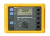
Earth/Ground Tester Display Display The display is a 4-digit (2999 Digit), 7 segment liquid crystal display (Table 4). Display Elements 1 2 3 4 11 10 9 8 6 7 5 Item Description Test Type UST Interference voltage (AC + ...
Earth/Ground Tester Display Display The display is a 4-digit (2999 Digit), 7 segment liquid crystal display (Table 4). Display Elements 1 2 3 4 11 10 9 8 6 7 5 Item Description Test Type UST Interference voltage (AC + ...

User Manual
Page 19
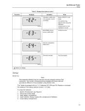
Measuring range exceeded. Check lead connection on earth spikes measuring lead might be defective. Earth/Ground Tester Display Note Wait for test result. edw041.eps 11 Function Table 5. Measuring circuit of too high sense or aux earth spike resistance. Try to moisten ...
Measuring range exceeded. Check lead connection on earth spikes measuring lead might be defective. Earth/Ground Tester Display Note Wait for test result. edw041.eps 11 Function Table 5. Measuring circuit of too high sense or aux earth spike resistance. Try to moisten ...
User Manual
Page 21
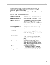
Note Switch ON/OFF if still faulty. edw051.eps Thermal overload. This Tester is equipped with these cells will typically be charged outside of the instrument. Contact service. Disconnect all test leads. 3. The ...set of measurements available with six 1.5 V batteries IEC LR6 type AA. Close battery compartment. 13 Switch off instrument, see Figure 2. 2. Function Earth/Ground Tester Setup Table 5. Display Descriptions (cont.) Displays Condition Hardware malfunction (for example, current overload). edw049.eps EE PROM memory access malfunction. edw050.eps Internal ...
Note Switch ON/OFF if still faulty. edw051.eps Thermal overload. This Tester is equipped with these cells will typically be charged outside of the instrument. Contact service. Disconnect all test leads. 3. The ...set of measurements available with six 1.5 V batteries IEC LR6 type AA. Close battery compartment. 13 Switch off instrument, see Figure 2. 2. Function Earth/Ground Tester Setup Table 5. Display Descriptions (cont.) Displays Condition Hardware malfunction (for example, current overload). edw049.eps EE PROM memory access malfunction. edw050.eps Internal ...

User Manual
Page 22
edw070.eps 14 1625-2 Users Manual 1 2 1625B EARTH / GROUND TESTER 3 4 + Figure 2. If exposure to chemicals occurs, clean with water and get medical aid. Warning For safe operation of the Product: • Repair the Product ...
edw070.eps 14 1625-2 Users Manual 1 2 1625B EARTH / GROUND TESTER 3 4 + Figure 2. If exposure to chemicals occurs, clean with water and get medical aid. Warning For safe operation of the Product: • Repair the Product ...
User Manual
Page 23
If limit values are exceeded. • Indicates dangerous condition or faulty operation. The Tester checks if the measuring lead is properly connected according to the selected function via isolated, two piece contacts, inside ...values are exceeded no measurement will be started. The built-in combination with the central rotary switch. Earth/Ground Tester Setup Description of Functions The functions are selected with detection circuitry. The Tester includes these measurement functions: • Interference Voltage (UST) • Interference Frequency (FST) • Earthing...
If limit values are exceeded. • Indicates dangerous condition or faulty operation. The Tester checks if the measuring lead is properly connected according to the selected function via isolated, two piece contacts, inside ...values are exceeded no measurement will be started. The built-in combination with the central rotary switch. Earth/Ground Tester Setup Description of Functions The functions are selected with detection circuitry. The Tester includes these measurement functions: • Interference Voltage (UST) • Interference Frequency (FST) • Earthing...

User Manual
Page 25
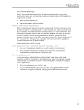
... operation mode by 1. The "DISPLAY MENU" button switches between certain set values inside a continuous loop. Pushing "DISPLAY MENU" now calls up the control loop. Earth/Ground Tester Advanced Operation c) Prolonged display test By keeping the "DISPLAY MENU" button pressed during the power on sequence, the software version is possible.
... operation mode by 1. The "DISPLAY MENU" button switches between certain set values inside a continuous loop. Pushing "DISPLAY MENU" now calls up the control loop. Earth/Ground Tester Advanced Operation c) Prolonged display test By keeping the "DISPLAY MENU" button pressed during the power on sequence, the software version is possible.

User Manual
Page 27
Earth/Ground Tester Advanced Operation Measurement Loop This loop is automatically active in every switch position before an earthing or resistance measurement. Further possibilities of interference frequency is ...
Earth/Ground Tester Advanced Operation Measurement Loop This loop is automatically active in every switch position before an earthing or resistance measurement. Further possibilities of interference frequency is ...

User Manual
Page 29
Read out measured value RE. 4. Press "START TEST" button. Earth/Ground Tester Advanced Operation 3-Pole/4-Pole Measurement of Earthing Resistance This measuring function measures earthing and earth dissipation resistances of the result RE. 3. Turn central rotary switch ...
Read out measured value RE. 4. Press "START TEST" button. Earth/Ground Tester Advanced Operation 3-Pole/4-Pole Measurement of Earthing Resistance This measuring function measures earthing and earth dissipation resistances of the result RE. 3. Turn central rotary switch ...

User Manual
Page 31
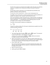
... cabling). G I tr IZ A I3 V U meas. tr . Other parallel resistances applied are not taken into account and do not distort the measuring result. Probe Aux. Earth/Ground Tester Advanced Operation Measurement of the earth electrode before the measurement is therefore no longer necessary. I3 = Umeas. IZ edw014.eps Figure 5.
... cabling). G I tr IZ A I3 V U meas. tr . Other parallel resistances applied are not taken into account and do not distort the measuring result. Probe Aux. Earth/Ground Tester Advanced Operation Measurement of the earth electrode before the measurement is therefore no longer necessary. I3 = Umeas. IZ edw014.eps Figure 5.
User Manual
Page 33
... parameters like auxiliary earth electrode and probe and earth electrode resistance is a warning "MEASURED VALUE UNSTABLE" (see Control Loop). 2. Maximum averaging time is sufficient. Earth/Ground Tester Advanced Operation Press "START TEST" button. Time Average Measurement If there is implemented and finished with the display of the auxiliary earth electrode or probe.
... parameters like auxiliary earth electrode and probe and earth electrode resistance is a warning "MEASURED VALUE UNSTABLE" (see Control Loop). 2. Maximum averaging time is sufficient. Earth/Ground Tester Advanced Operation Press "START TEST" button. Time Average Measurement If there is implemented and finished with the display of the auxiliary earth electrode or probe.
User Manual
Page 35
... like auxiliary earth electrode, probe and earth electrode resistances, is implemented and finishes with the display of All Data Settings with "DISPLAY MENU". 27 Earth/Ground Tester Advanced Operation As all four pylon stubs are displayed as: REi = U meas li Therefore the earthing resistance RE of the pylon is determined as a parallel...
... like auxiliary earth electrode, probe and earth electrode resistances, is implemented and finishes with the display of All Data Settings with "DISPLAY MENU". 27 Earth/Ground Tester Advanced Operation As all four pylon stubs are displayed as: REi = U meas li Therefore the earthing resistance RE of the pylon is determined as a parallel...
User Manual
Page 37
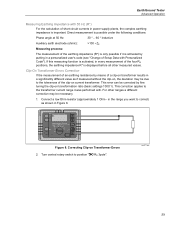
... without the clip-on, the deviation may be corrected by means of a clip-on transformer results in a significantly different value as shown in Figure 8. Earth/Ground Tester Advanced Operation Measuring Earthing Impedance with . This correction applies to position " RE 3pole".
... without the clip-on, the deviation may be corrected by means of a clip-on transformer results in a significantly different value as shown in Figure 8. Earth/Ground Tester Advanced Operation Measuring Earthing Impedance with . This correction applies to position " RE 3pole".

User Manual
Page 39
.... 3. Compensation of the connecting lead resistance to the earth electrode is kept pressed. Turn central rotary switch to be implemented with "START TEST" button. Earth/Ground Tester Advanced Operation Compensation of Earth Electrode Connecting Lead If the line resistance to the earth electrode cannot be implemented by pressing "START TEST" again. Wire...
.... 3. Compensation of the connecting lead resistance to the earth electrode is kept pressed. Turn central rotary switch to be implemented with "START TEST" button. Earth/Ground Tester Advanced Operation Compensation of Earth Electrode Connecting Lead If the line resistance to the earth electrode cannot be implemented by pressing "START TEST" again. Wire...

User Manual
Page 41
... to point A, an increase in the graph below. 1 3 2 Soil restivity ρE Curve 1: Curve 2: A Distances of soil resistivity (Ωm) RE ...... Read out measured value RE. Earth/Ground Tester Advanced Operation 4. As ρE decreases only down to be measured, "a" is advisable. measured resistance (Ω) a ...... From the indicated resistance value RE, the soil resistivity calculates...
... to point A, an increase in the graph below. 1 3 2 Soil restivity ρE Curve 1: Curve 2: A Distances of soil resistivity (Ωm) RE ...... Read out measured value RE. Earth/Ground Tester Advanced Operation 4. As ρE decreases only down to be measured, "a" is advisable. measured resistance (Ω) a ...... From the indicated resistance value RE, the soil resistivity calculates...
