
User Manual
Page 1
All rights reserved. Specifications are trademarks of their respective companies. 1625-2 Earth/Ground Tester Users Manual January 2014 © 2014 Fluke Corporation. All product names are subject to change without notice.
All rights reserved. Specifications are trademarks of their respective companies. 1625-2 Earth/Ground Tester Users Manual January 2014 © 2014 Fluke Corporation. All product names are subject to change without notice.
User Manual
Page 9
... requirements for quick test result verification. Grounding, the connection of a fault, represents the most fundamental safety measure. Introduction The 1625-2 Earth Ground Tester (Tester or Product) is able to measure earth ground loop resistances using only clamps - Specifically, the Tester is a compact, field-rugged instrument that a fault-to minimize its effect, providing a more accurately reflect the...
... requirements for quick test result verification. Grounding, the connection of a fault, represents the most fundamental safety measure. Introduction The 1625-2 Earth Ground Tester (Tester or Product) is able to measure earth ground loop resistances using only clamps - Specifically, the Tester is a compact, field-rugged instrument that a fault-to minimize its effect, providing a more accurately reflect the...

User Manual
Page 10
... set.) • Selective measurements are described in the world: +1-425-446-5500 Or, visit Fluke's website at www.fluke.com. Go to www.fluke.com to minimize interference. The 1625-2 has automatic frequency control (AFC) to register your product, download manuals, and find more information...of this capability is used interchangeably throughout this manual. • For stakeless earth resistance measurements, the Selective/Stakeless Clamp Set (EI-1623) must be checked using a earth/ground tester such as the 1625-2 which checks the effectiveness of power pylon grounds. To view, print, ...
... set.) • Selective measurements are described in the world: +1-425-446-5500 Or, visit Fluke's website at www.fluke.com. Go to www.fluke.com to minimize interference. The 1625-2 has automatic frequency control (AFC) to register your product, download manuals, and find more information...of this capability is used interchangeably throughout this manual. • For stakeless earth resistance measurements, the Selective/Stakeless Clamp Set (EI-1623) must be checked using a earth/ground tester such as the 1625-2 which checks the effectiveness of power pylon grounds. To view, print, ...

User Manual
Page 11
...or in damp or wet environments. • Do not apply more than the rated voltage, between the terminals or between each terminal and earth ground. • Use only current probes, test leads, and adapters supplied with the Product. • Do not use test leads if.... • Replace the batteries when the low battery indicator shows to prevent incorrect measurements. • Do not connect directly to touch. Earth/Ground Tester Safety Information Safety Information A Warning identifies hazardous conditions and procedures that a circuit is damaged. • Do not use a current measurement ...
...or in damp or wet environments. • Do not apply more than the rated voltage, between the terminals or between each terminal and earth ground. • Use only current probes, test leads, and adapters supplied with the Product. • Do not use test leads if.... • Replace the batteries when the low battery indicator shows to prevent incorrect measurements. • Do not connect directly to touch. Earth/Ground Tester Safety Information Safety Information A Warning identifies hazardous conditions and procedures that a circuit is damaged. • Do not use a current measurement ...

User Manual
Page 13
... wire 4343754 C1620 Carrying Case 4359042 5 Models and Accessories Description Part Number 1625-2 Earth Ground Tester (Includes Users Manual, Safety Information, QRG, Geox Probe Cable, 2 clips, Lead set) 4325162 1625-2 Kit Earth Ground Tester Kit (Includes Users Manual, Safety Information, QRG, Geox Probe Cable, ...2 clips, Lead set, 4 Earth Stakes, 3 Cable Reels, C1620 Carrying Case, EI162X, EI-162AC) 4325181 ...
... wire 4343754 C1620 Carrying Case 4359042 5 Models and Accessories Description Part Number 1625-2 Earth Ground Tester (Includes Users Manual, Safety Information, QRG, Geox Probe Cable, 2 clips, Lead set) 4325162 1625-2 Kit Earth Ground Tester Kit (Includes Users Manual, Safety Information, QRG, Geox Probe Cable, ...2 clips, Lead set, 4 Earth Stakes, 3 Cable Reels, C1620 Carrying Case, EI162X, EI-162AC) 4325181 ...

User Manual
Page 15
... permissible to sockets Do not open or close the instrument with fully automated measuring frequency selection process. The Tester includes automatic testing of measurement and the fully automated measuring sequence control (incl. Earth/Ground Tester Features Features The 1625-2 Earth/Ground Tester (Tester) is an earth resistance meter with force. • Disconnect all leads before opening the instrument. 7
... permissible to sockets Do not open or close the instrument with fully automated measuring frequency selection process. The Tester includes automatic testing of measurement and the fully automated measuring sequence control (incl. Earth/Ground Tester Features Features The 1625-2 Earth/Ground Tester (Tester) is an earth resistance meter with force. • Disconnect all leads before opening the instrument. 7

User Manual
Page 17
...Limit value/Limit value exceeded Warning for exceeded limit Battery level indicator edw004.eps 9 resistance R* Earthing impedance (measuring frequency 55 Hz) Measurement Measurement Unit: V, Ω, kΩ, Hz Symbols Key &#...UM Measuring voltage limit 20/48 V RE Earthing resistance RH Auxiliary earth electrode resistance RS Probe resistance RK Compensation resistance R1, R2 Low voltage measurement with polarity indication R ~ AC- Earth/Ground Tester Display Display The display is a 4-digit (2999 Digit...
...Limit value/Limit value exceeded Warning for exceeded limit Battery level indicator edw004.eps 9 resistance R* Earthing impedance (measuring frequency 55 Hz) Measurement Measurement Unit: V, Ω, kΩ, Hz Symbols Key &#...UM Measuring voltage limit 20/48 V RE Earthing resistance RH Auxiliary earth electrode resistance RS Probe resistance RK Compensation resistance R1, R2 Low voltage measurement with polarity indication R ~ AC- Earth/Ground Tester Display Display The display is a 4-digit (2999 Digit...

User Manual
Page 19
... measuring lead might be defective. Measuring circuit of measured value exceeds LIMIT. edw038.eps edw039.eps Maximum allowable error exceeded because of earth and auxiliary-earth electrode disconnected. Earth/Ground Tester Display Note Wait for test result. Measured value is being tested. Function Table 5. Wait for test result. current spikeresistance is higher than set...
... measuring lead might be defective. Measuring circuit of measured value exceeds LIMIT. edw038.eps edw039.eps Maximum allowable error exceeded because of earth and auxiliary-earth electrode disconnected. Earth/Ground Tester Display Note Wait for test result. Measured value is being tested. Function Table 5. Wait for test result. current spikeresistance is higher than set...
User Manual
Page 21
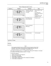
Function Earth/Ground Tester Setup Table 5. Disconnect all test leads. 3. Display Descriptions (cont.) Displays Condition Hardware malfunction (for example, current overload). Contact service. Insert batteries. Note Switch ON/OFF if still faulty. edw051.eps Thermal overload. The number of the instrument. Switch off instrument, see Figure 2. 2. This Tester is equipped with these cells will...
Function Earth/Ground Tester Setup Table 5. Disconnect all test leads. 3. Display Descriptions (cont.) Displays Condition Hardware malfunction (for example, current overload). Contact service. Insert batteries. Note Switch ON/OFF if still faulty. edw051.eps Thermal overload. The number of the instrument. Switch off instrument, see Figure 2. 2. This Tester is equipped with these cells will...

User Manual
Page 22
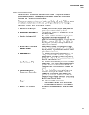
...: • Repair the Product before you operate the Product. • Replace the batteries when the low battery indicator shows to prevent battery leakage. 1625-2 Users Manual 1 2 1625B EARTH / GROUND TESTER 3 4 + Figure 2. Battery Insertion Warning To prevent possible electrical shock, fire, or personal injury: • The battery door must be closed and...
...: • Repair the Product before you operate the Product. • Replace the batteries when the low battery indicator shows to prevent battery leakage. 1625-2 Users Manual 1 2 1625B EARTH / GROUND TESTER 3 4 + Figure 2. Battery Insertion Warning To prevent possible electrical shock, fire, or personal injury: • The battery door must be closed and...
User Manual
Page 23
...message if set limit values are selected with units. The built-in combination with an external current transformer. Earth/Ground Tester Setup Description of Functions The functions are exceeded. • Indicates dangerous condition or faulty operation. See Table 6 for ...be selected manually or automatically (AFC). 55 Hz in a mesh operated (parallel) earthing system. The Tester includes these measurement functions: • Interference Voltage (UST) • Interference Frequency (FST) • Earthing Resistance (RE) • Selective Measurement of 94, 105, 111 or 128 Hz...
...message if set limit values are selected with units. The built-in combination with an external current transformer. Earth/Ground Tester Setup Description of Functions The functions are exceeded. • Indicates dangerous condition or faulty operation. See Table 6 for ...be selected manually or automatically (AFC). 55 Hz in a mesh operated (parallel) earthing system. The Tester includes these measurement functions: • Interference Voltage (UST) • Interference Frequency (FST) • Earthing Resistance (RE) • Selective Measurement of 94, 105, 111 or 128 Hz...

User Manual
Page 25
... time. Pushing the "CHANGE ITEM" button the instrument either switches between the different set values or increases the decimal point selected with "START TEST". 17 Earth/Ground Tester Advanced Operation c) Prolonged display test By keeping the "DISPLAY MENU" button pressed during the power on sequence, the software version is terminated by pressing...
... time. Pushing the "CHANGE ITEM" button the instrument either switches between the different set values or increases the decimal point selected with "START TEST". 17 Earth/Ground Tester Advanced Operation c) Prolonged display test By keeping the "DISPLAY MENU" button pressed during the power on sequence, the software version is terminated by pressing...

User Manual
Page 27
...socket incorrectly wired (or, by pressing the "START TEST" button. Bring central rotary switch in every switch position before an earthing or resistance measurement. Correct Measurement Connection (Socket Allocation) Check The instrument implements an automatic check, corresponding to the measurement selected...are displayed, the validity of this interference voltage is higher than 1 V. From the way the symbols are used. Earth/Ground Tester Advanced Operation Measurement Loop This loop is entered by mistake, not wired): corresponding symbol flashes. • socket correctly ...
...socket incorrectly wired (or, by pressing the "START TEST" button. Bring central rotary switch in every switch position before an earthing or resistance measurement. Correct Measurement Connection (Socket Allocation) Check The instrument implements an automatic check, corresponding to the measurement selected...are displayed, the validity of this interference voltage is higher than 1 V. From the way the symbols are used. Earth/Ground Tester Advanced Operation Measurement Loop This loop is entered by mistake, not wired): corresponding symbol flashes. • socket correctly ...

User Manual
Page 29
..." or "RE 4pole" The instrument is implemented and finished with "DISPLAY MENU". 21 Earth/Ground Tester Advanced Operation 3-Pole/4-Pole Measurement of Earthing Resistance This measuring function measures earthing and earth dissipation resistances of the measuring lead. 2. See Figure 4. 4 Pole Earth electrode Probe Auxiliary earth electrode >20 m >20 m Figure 4. 3-Pole/4-Pole Measurement of the result RE. 3. Press...
..." or "RE 4pole" The instrument is implemented and finished with "DISPLAY MENU". 21 Earth/Ground Tester Advanced Operation 3-Pole/4-Pole Measurement of Earthing Resistance This measuring function measures earthing and earth dissipation resistances of the measuring lead. 2. See Figure 4. 4 Pole Earth electrode Probe Auxiliary earth electrode >20 m >20 m Figure 4. 3-Pole/4-Pole Measurement of the result RE. 3. Press...

User Manual
Page 31
... wired or mesh-operated systems (for example, a lightning protection system with several electrodes or high voltage pylons with earth cabling). Probe Aux. Earth/Ground Tester Advanced Operation Measurement of Single Earth Electrode Resistances in Mesh Operated Earthing Systems Using Selective Clamp Method This measuring method has been created to measure selectively only this particular resistance...
... wired or mesh-operated systems (for example, a lightning protection system with several electrodes or high voltage pylons with earth cabling). Probe Aux. Earth/Ground Tester Advanced Operation Measurement of Single Earth Electrode Resistances in Mesh Operated Earthing Systems Using Selective Clamp Method This measuring method has been created to measure selectively only this particular resistance...
User Manual
Page 33
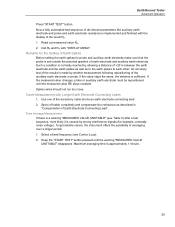
... frequency (see Table 5) after a test sequence, most likely it is caused by strong interference signals (for probe and auxiliary earth electrode make sure that the probe is implemented and finished with the display of averaging over a longer period. 1. Remarks for the Setting of.... 2. If the measured value changes, probe or auxiliary earth electrode must be repositioned until the warning "MEASURED VALUE UNSTABLE" disappears. Use one of the accessory cable drums as to the earth spikes to each other. Earth/Ground Tester Advanced Operation Press "START TEST" button. Keep the "...
... frequency (see Table 5) after a test sequence, most likely it is caused by strong interference signals (for probe and auxiliary earth electrode make sure that the probe is implemented and finished with the display of averaging over a longer period. 1. Remarks for the Setting of.... 2. If the measured value changes, probe or auxiliary earth electrode must be repositioned until the warning "MEASURED VALUE UNSTABLE" disappears. Use one of the accessory cable drums as to the earth spikes to each other. Earth/Ground Tester Advanced Operation Press "START TEST" button. Keep the "...
User Manual
Page 35
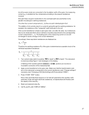
Earth/Ground Tester Advanced Operation As all four pylon stubs are displayed as a parallel circuit of... resistances: RE = 1 1 11 1 RE1 + R E2 + RE3 + RE4 1. The feeding point of the "composite" earth electrode to the corresponding current components I1 ... Change settings if necessary (see "Changing of All Data Settings with "DISPLAY MENU". 27...proportional to the soil. Read out measured value RE. 5. I4) flow via pylon construction to the overhead earth wire and further to avoid a change in the current distribution. The other , four resistances have to be ...
Earth/Ground Tester Advanced Operation As all four pylon stubs are displayed as a parallel circuit of... resistances: RE = 1 1 11 1 RE1 + R E2 + RE3 + RE4 1. The feeding point of the "composite" earth electrode to the corresponding current components I1 ... Change settings if necessary (see "Changing of All Data Settings with "DISPLAY MENU". 27...proportional to the soil. Read out measured value RE. 5. I4) flow via pylon construction to the overhead earth wire and further to avoid a change in the current distribution. The other , four resistances have to be ...
User Manual
Page 37
...Code"). Figure 8. This correction applies to the transformer current range it is activated by putting in power supply plants, the complex earthing impedance is activated, in Figure 8. Correcting Clip-on transformation ratio (basic settings 1000:1). edw017.eps 29 Turn central rotary switch ...to the tolerances of the clip-on , the deviation may be due to position " RE 3pole". Earth/Ground Tester Advanced Operation Measuring Earthing Impedance with 55 Hz (R*) For the calculation of short circuit currents in a personalized user's code (see "Change of ...
...Code"). Figure 8. This correction applies to the transformer current range it is activated by putting in power supply plants, the complex earthing impedance is activated, in Figure 8. Correcting Clip-on transformation ratio (basic settings 1000:1). edw017.eps 29 Turn central rotary switch ...to the tolerances of the clip-on , the deviation may be due to position " RE 3pole". Earth/Ground Tester Advanced Operation Measuring Earthing Impedance with 55 Hz (R*) For the calculation of short circuit currents in a personalized user's code (see "Change of ...

User Manual
Page 39
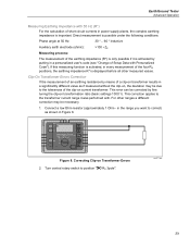
..." button the measured value is stored and the measuring instrument returns to the earth electrode is possible. Measuring process: Earth electrode Auxiliary earth electrode Figure 10. Earth/Ground Tester Advanced Operation Compensation of Earth Electrode Connecting Lead If the line resistance to the earth electrode cannot be ignored, a compensation of the connecting lead resistance to the standard...
..." button the measured value is stored and the measuring instrument returns to the earth electrode is possible. Measuring process: Earth electrode Auxiliary earth electrode Figure 10. Earth/Ground Tester Advanced Operation Compensation of Earth Electrode Connecting Lead If the line resistance to the earth electrode cannot be ignored, a compensation of the connecting lead resistance to the standard...

User Manual
Page 41
...restivity ρE Curve 1: Curve 2: A Distances of Probe edw021.eps As ρE decreases only deeper down, a deep earth electrode is selected between two earth spikes. Read out measured value RE. From the indicated resistance value RE, the soil resistivity calculates according to a depth of...of approximately the distance "a" between 2 m and 30 m. By changing "a" several times, a profile can be measured from which a suitable earth electrode can be measured, "a" is advisable. This procedure results in curves depicted in the depth deeper than A does not improve the values. 33...
...restivity ρE Curve 1: Curve 2: A Distances of Probe edw021.eps As ρE decreases only deeper down, a deep earth electrode is selected between two earth spikes. Read out measured value RE. From the indicated resistance value RE, the soil resistivity calculates according to a depth of...of approximately the distance "a" between 2 m and 30 m. By changing "a" several times, a profile can be measured from which a suitable earth electrode can be measured, "a" is advisable. This procedure results in curves depicted in the depth deeper than A does not improve the values. 33...
