
Installation Instructions
Page 1
Installation Instructions Electrolux Front-Load Gas a Electric Dryer E Electrolux 1)701820) A 10e0i I
Installation Instructions Electrolux Front-Load Gas a Electric Dryer E Electrolux 1)701820) A 10e0i I

Installation Instructions
Page 2
...www.electroluxapvilances.com or Dy ciroppinc yourProduct Registration Cara in home appliances. Ges dryer 11 Electrical connection - Bectric dryer (4-wirecacq...13 Gee oarnectian 14 Water connection (Steam Model only) 15-16 General installation 17 Performing installs:bar cycle is Resenting... Electric dryer 10 • Gn:undng reatirements - Elect& dryer (3-wIre call... 12 Electrical connection - To oncuro our abltty to continuo coming you for quick reference Purchase date Electrolux motel nunDer Electrolux serial nuirber NOTE Registering your proauct with Electrolux ...
...www.electroluxapvilances.com or Dy ciroppinc yourProduct Registration Cara in home appliances. Ges dryer 11 Electrical connection - Bectric dryer (4-wirecacq...13 Gee oarnectian 14 Water connection (Steam Model only) 15-16 General installation 17 Performing installs:bar cycle is Resenting... Electric dryer 10 • Gn:undng reatirements - Elect& dryer (3-wIre call... 12 Electrical connection - To oncuro our abltty to continuo coming you for quick reference Purchase date Electrolux motel nunDer Electrolux serial nuirber NOTE Registering your proauct with Electrolux ...

Installation Instructions
Page 3
... this manual and all of the National Eledilcal Code. ANSI/ NFPA 70, or in Canada, the Canadian electrical code C22.1 part 1. • The gas senAce tothe dryer must conform with local codes and ordinances and the latest edi- Follow the gassuppliers instructions. • i ...arsightt Adjumable plin NUM bib actesdivere wrench - This symbol alerts you to the rrenutacturers instructions and boat codes. • The electrical seiviceto the dryer must conform with local codes and ordinances and the latest edition of the following hstructIons before instarung and temp tme appuanco: &#...
... this manual and all of the National Eledilcal Code. ANSI/ NFPA 70, or in Canada, the Canadian electrical code C22.1 part 1. • The gas senAce tothe dryer must conform with local codes and ordinances and the latest edi- Follow the gassuppliers instructions. • i ...arsightt Adjumable plin NUM bib actesdivere wrench - This symbol alerts you to the rrenutacturers instructions and boat codes. • The electrical seiviceto the dryer must conform with local codes and ordinances and the latest edition of the following hstructIons before instarung and temp tme appuanco: &#...
Installation Instructions
Page 4
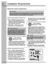
... CON] (NEMA 1,1-3OR). Zwire, with cbthes Myers For 3-wire corn connection Instructions see ELECTRICAL CONNECTIONS FOR A 4-WIRE SYSTEM. mind pavered generators or any otner generator °alp tnan the local utility company I* not recommended. GROUNDING CONNECTION - Electrical requirements for electric dryer. CIRCUIT - Use separately fused circuits for US) with ground, 12O volt, single phase...
... CON] (NEMA 1,1-3OR). Zwire, with cbthes Myers For 3-wire corn connection Instructions see ELECTRICAL CONNECTIONS FOR A 4-WIRE SYSTEM. mind pavered generators or any otner generator °alp tnan the local utility company I* not recommended. GROUNDING CONNECTION - Electrical requirements for electric dryer. CIRCUIT - Use separately fused circuits for US) with ground, 12O volt, single phase...
Installation Instructions
Page 5
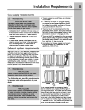
.... Exhaust system requirements 4. The gas supply Ilne MUST -rave an Individual shutoff valve. 5. A 1/8 inch ((.92 cm) N.P.T. e. The aryer MUST be 1/2 Inch (1.27 cm) pipe. 3 it with flexible plastic or metal fon val1Ing MaterlaS. U. In Canada and the United Mates If metal (toll type) duct is installed, It ...nee of 12 tales (30.5 an) clearance between the vent hood aid the ground or any lint prior to instal ing dryer duct. WARNING FIRE HAZARD Do not Install a oomes dryer with a rigid or sell-rigid metal duct. Coned c:b 6h kcanct If present system Is made up of tne gas supply...
.... Exhaust system requirements 4. The gas supply Ilne MUST -rave an Individual shutoff valve. 5. A 1/8 inch ((.92 cm) N.P.T. e. The aryer MUST be 1/2 Inch (1.27 cm) pipe. 3 it with flexible plastic or metal fon val1Ing MaterlaS. U. In Canada and the United Mates If metal (toll type) duct is installed, It ...nee of 12 tales (30.5 an) clearance between the vent hood aid the ground or any lint prior to instal ing dryer duct. WARNING FIRE HAZARD Do not Install a oomes dryer with a rigid or sell-rigid metal duct. Coned c:b 6h kcanct If present system Is made up of tne gas supply...
Installation Instructions
Page 6
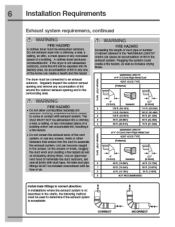
... hazard. a wail a ceiling, an attic, a crawl space or any concealed space of the noire can create a realth ana tire nazara Tne dryer must ce used to assemb the exhaust system. of a building which can cause an accumulation of 4' O0.2errosemmiold meta oist 5 VENT HOOD TYPE ...arel. All male duct pipe fittings MUST be exhausted outdoors. 6 Installation Requirements Exhaust system requirements, continued WARNING FIRE HAZARD A clothes dryer mug be nstaiied aownstream with exhaust system. and seal all pints witnauct tape. MAIMUM LENGTH we the exhaust system is not exhausted outdoors...
... hazard. a wail a ceiling, an attic, a crawl space or any concealed space of the noire can create a realth ana tire nazara Tne dryer must ce used to assemb the exhaust system. of a building which can cause an accumulation of 4' O0.2errosemmiold meta oist 5 VENT HOOD TYPE ...arel. All male duct pipe fittings MUST be exhausted outdoors. 6 Installation Requirements Exhaust system requirements, continued WARNING FIRE HAZARD A clothes dryer mug be nstaiied aownstream with exhaust system. and seal all pints witnauct tape. MAIMUM LENGTH we the exhaust system is not exhausted outdoors...

Installation Instructions
Page 7
... Is too restilotIve and tne installation Is unacceptable. explosion. lithe manometer reading Is higher than helve the area of the dryer exhaust outlet. Manufactured or mobile home installation 1 installation MUST contain to mhaust outlet of every 18 monthswith normal usage. ... causing an increase in death. Installation Requirements 7 Exhaust system requirements, ccntinued th WARNING EXPLOSION HAZARD Do not install tie dryer whale gasoline or other important exhaust venting system requirements. 5. If the Lem is nstaileci in 0lameter with the teminatlon securely...
... Is too restilotIve and tne installation Is unacceptable. explosion. lithe manometer reading Is higher than helve the area of the dryer exhaust outlet. Manufactured or mobile home installation 1 installation MUST contain to mhaust outlet of every 18 monthswith normal usage. ... causing an increase in death. Installation Requirements 7 Exhaust system requirements, ccntinued th WARNING EXPLOSION HAZARD Do not install tie dryer whale gasoline or other important exhaust venting system requirements. 5. If the Lem is nstaileci in 0lameter with the teminatlon securely...

Installation Instructions
Page 8
...IOUV9I9d door %vitt equivalent air openingstorthefull length of opening, equally divided atthetop and bottom ot the door, Is required. a q ick-tum 9CP dryer vent elbow must be iocatec Inctos (7.8 cm) from bottom and top of 1 incn (2.54 cm). MUST be Installed In the same closet ...IInds:tr. Closet dcor ventilation required: A minimum ot 120 square inches (774.2 cm") of tle door Is acceptable. z. Openings should be installed as the gas dryer. 3. Floor MUST besolla with 0" (0 cm) clearance tor the back Of the direr (for ',toper ventilation. U. °CM) VOGT,' If (., cm)...
...IOUV9I9d door %vitt equivalent air openingstorthefull length of opening, equally divided atthetop and bottom ot the door, Is required. a q ick-tum 9CP dryer vent elbow must be iocatec Inctos (7.8 cm) from bottom and top of 1 incn (2.54 cm). MUST be Installed In the same closet ...IInds:tr. Closet dcor ventilation required: A minimum ot 120 square inches (774.2 cm") of tle door Is acceptable. z. Openings should be installed as the gas dryer. 3. Floor MUST besolla with 0" (0 cm) clearance tor the back Of the direr (for ',toper ventilation. U. °CM) VOGT,' If (., cm)...
Installation Instructions
Page 9
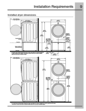
Installation Requirements 9 AIM Installed dryer dimensions ferroideiny to dampen door ea Mel as dear (Oder, O ter assn gest IleceNns J Oar (110.Sal sr, IsId.la tv-wft re".7 dive navitid *...
Installation Requirements 9 AIM Installed dryer dimensions ferroideiny to dampen door ea Mel as dear (Oder, O ter assn gest IleceNns J Oar (110.Sal sr, IsId.la tv-wft re".7 dive navitid *...

Installation Instructions
Page 10
...are specific requirements fa proper ana safe electrical Intelteflon or your dryer. NOTE Dryers operating on 240 volt power supply. cord-ponnectea dryer 1. copper wired receptacle tnat is not propeny grounaea. The dryer MUST be purchased. Follow tne instructions in... having an equipmentgrounding conauctor and a grounding plug trot matcheo ycuwinng oyatem. For a grounded. Locate tne dryer within reach of least resistance forelectncal current. 2. WARNING ELECTRICAL SHOCK HAZARD e This appliance MUST Cer propeny grounclea. Grounding requirements - Fur re to be grounded....
...are specific requirements fa proper ana safe electrical Intelteflon or your dryer. NOTE Dryers operating on 240 volt power supply. cord-ponnectea dryer 1. copper wired receptacle tnat is not propeny grounaea. The dryer MUST be purchased. Follow tne instructions in... having an equipmentgrounding conauctor and a grounding plug trot matcheo ycuwinng oyatem. For a grounded. Locate tne dryer within reach of least resistance forelectncal current. 2. WARNING ELECTRICAL SHOCK HAZARD e This appliance MUST Cer propeny grounclea. Grounding requirements - Fur re to be grounded....
Installation Instructions
Page 11
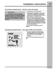
...local cones and orcinances. DO NOT cut or remove ground prong from the pitg. Power coed with the ap)liance. Electrb dryer (Canada) A\ WARNING ELECTRICAL SHCCK HAZARD improper ccnnection of trio equipment grounding conductor can Neuit in a rm< 07 oicetnoai snocic Check vita a ricenson ...electrician if you are in doubt. DO NOT moony the plug provned with 3-Pron9 ~dad ISO Gas dryer (USA and Canada) a,fii LQantz.) grameoll ...
...local cones and orcinances. DO NOT cut or remove ground prong from the pitg. Power coed with the ap)liance. Electrb dryer (Canada) A\ WARNING ELECTRICAL SHCCK HAZARD improper ccnnection of trio equipment grounding conductor can Neuit in a rm< 07 oicetnoai snocic Check vita a ricenson ...electrician if you are in doubt. DO NOT moony the plug provned with 3-Pron9 ~dad ISO Gas dryer (USA and Canada) a,fii LQantz.) grameoll ...

Installation Instructions
Page 12
12 Installation Instructions Electrical connection (non-Canada) - 3 wire cord 3-wire receptacle %00 (NEMA type 10-30R) /?\ WARNING ELECTRICAL SHOCK HAZARD Failure to
12 Installation Instructions Electrical connection (non-Canada) - 3 wire cord 3-wire receptacle %00 (NEMA type 10-30R) /?\ WARNING ELECTRICAL SHOCK HAZARD Failure to
Installation Instructions
Page 13
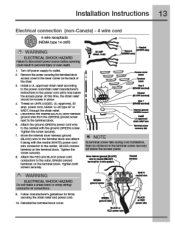
... the screw securcly. 7 Move the internal dryer Maness ground (BLACK) wire to the terminal dock and attach It along With tne neutral (WHITE) power cord wire conductor to tne cabinet with tne ground (GREEN) screw. Tighten both screws %CUrely. ?\ WARNING ELECTRICAL SHCCK HAZARD Do not make a snarp bend...in tne terminal screw recovery sbt below the access panel. Reinstall tne terminal deck cover. through the strain rater. 5 Disconnect the Internal (BLACK) dryer harness ground wine iron) the (GFEEN) ground screw next to the terminal wick. 8 Attach the grouna (GREEN) power cord wire to tne center...
... the screw securcly. 7 Move the internal dryer Maness ground (BLACK) wire to the terminal dock and attach It along With tne neutral (WHITE) power cord wire conductor to tne cabinet with tne ground (GREEN) screw. Tighten both screws %CUrely. ?\ WARNING ELECTRICAL SHCCK HAZARD Do not make a snarp bend...in tne terminal screw recovery sbt below the access panel. Reinstall tne terminal deck cover. through the strain rater. 5 Disconnect the Internal (BLACK) dryer harness ground wine iron) the (GFEEN) ground screw next to the terminal wick. 8 Attach the grouna (GREEN) power cord wire to tne center...

Installation Instructions
Page 14
MI IMPORTANT DO NOT connect tna Remove the snipping cap from gas pipe at the near ot the dryer. 14 Installation Instructions Gas connection 1.
MI IMPORTANT DO NOT connect tna Remove the snipping cap from gas pipe at the near ot the dryer. 14 Installation Instructions Gas connection 1.
Installation Instructions
Page 16
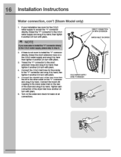
then tighten It another 2'3 turn with pliers. lighten each correction ot the dryer Inlet hose another 2/3 turn with pliers. 4. 16 Installation Instructions Water connection, con't (Steam Model only) 1. re NOTE Ityou wereabletoInstalthe"r connector direct to the COLD water supply, please slUp to tho Crass wator Inlot on the "V" connector and snug ... tighten It another 2/3 turn with pliers. 5. Connect the COLD Inlet hose for leaks at an corrections. then tight an Il miotlisi wlha pima. S. of the dryer and snug it by hand;
then tighten It another 2'3 turn with pliers. lighten each correction ot the dryer Inlet hose another 2/3 turn with pliers. 4. 16 Installation Instructions Water connection, con't (Steam Model only) 1. re NOTE Ityou wereabletoInstalthe"r connector direct to the COLD water supply, please slUp to tho Crass wator Inlot on the "V" connector and snug ... tighten It another 2/3 turn with pliers. 5. Connect the COLD Inlet hose for leaks at an corrections. then tight an Il miotlisi wlha pima. S. of the dryer and snug it by hand;
Installation Instructions
Page 17
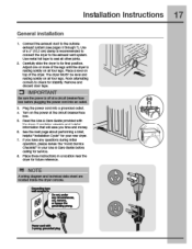
...tourlegs. M IMPORTANT Be sure the power Is off at a =nit bnaaltar/tuse box before calling for seivice. 8 Place these Inshucticrts n a location near the dryer for statillty. r Domtunder ;Awls** 14/ . 9muleV/Perill L %CO use motet fog tape to check for future reference. Place a level on top of... Into a grounded outlet. 4 Awn on the power at thecituft breaker/fuse box. 5 Read the Use & Care Guide provided with the dryer. NOTE I A wiring diagram and technixil data sheet are located inside the dryercc:rude. Installation Instructions 17 General installation 1 Connect the exhaust duct...
...tourlegs. M IMPORTANT Be sure the power Is off at a =nit bnaaltar/tuse box before calling for seivice. 8 Place these Inshucticrts n a location near the dryer for statillty. r Domtunder ;Awls** 14/ . 9muleV/Perill L %CO use motet fog tape to check for future reference. Place a level on top of... Into a grounded outlet. 4 Awn on the power at thecituft breaker/fuse box. 5 Read the Use & Care Guide provided with the dryer. NOTE I A wiring diagram and technixil data sheet are located inside the dryercc:rude. Installation Instructions 17 General installation 1 Connect the exhaust duct...

Installation Instructions
Page 18
WARNING FIRE HAZARD Beforeoperating thedryer.make to necessary corrections tetre you plug in the dryer tne first time: wake m the dryer Dy pressing any button, rotate cycle knob to ' correct cord connection (at electric MCCIGIS), presence ot gas supply (on . and other rnmmanie yams Aiso SOO that rattling (such... alt It0X05. Ai• 0 1.Empty the dryer arum. 2.Atter you plug in the dryer tne list time: wake ip the dryer by pressing any Dutton and 'follow...
WARNING FIRE HAZARD Beforeoperating thedryer.make to necessary corrections tetre you plug in the dryer tne first time: wake m the dryer Dy pressing any button, rotate cycle knob to ' correct cord connection (at electric MCCIGIS), presence ot gas supply (on . and other rnmmanie yams Aiso SOO that rattling (such... alt It0X05. Ai• 0 1.Empty the dryer arum. 2.Atter you plug in the dryer tne list time: wake ip the dryer by pressing any Dutton and 'follow...
Installation Instructions
Page 19
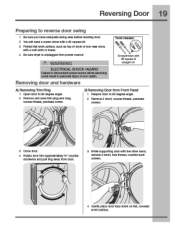
...door 2 You will need a screw driver with a t2 square bit. 3 Protect flat woik surface, such as top of dryer or11)or near dryer, with a soft cloth or towel. 4 Be sure dryer Is unplucged from Front Panel 1 Reopen door to 90 dogma angle. 2 Remove and save trim plug and long, course-...thread, panheed screw. B)Removing Door from power source) th WARNING ELECTRICAL SHOCK HkZARD Failureto disconnect power source Iatom savicIng could result in persona ...
...door 2 You will need a screw driver with a t2 square bit. 3 Protect flat woik surface, such as top of dryer or11)or near dryer, with a soft cloth or towel. 4 Be sure dryer Is unplucged from Front Panel 1 Reopen door to 90 dogma angle. 2 Remove and save trim plug and long, course-...thread, panheed screw. B)Removing Door from power source) th WARNING ELECTRICAL SHOCK HkZARD Failureto disconnect power source Iatom savicIng could result in persona ...
Installation Instructions
Page 20
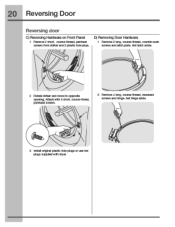
Iy D) Removing Door Hardware 1 Remove 2 Iamb course-thread. recessed screws and hinge. Set hinge aside. 3 Install nal plastic hole plugs or use new plugs suppliedwith dryer. couise-trireai, pannead scams. 2 Remove 4 Iamb course-thread. 20 Reversing Door Reversing door C) Reversing Hardware on Front Panel 1 Remove 2 slut, course-thread, panhead screws trom sinker and 2 plastic hole plugs. Mt:at-Iwith 2 short. Set latch aside. 2 Rotate striker and movetooppsite opening. counter-surd( screws and latch plate.
Iy D) Removing Door Hardware 1 Remove 2 Iamb course-thread. recessed screws and hinge. Set hinge aside. 3 Install nal plastic hole plugs or use new plugs suppliedwith dryer. couise-trireai, pannead scams. 2 Remove 4 Iamb course-thread. 20 Reversing Door Reversing door C) Reversing Hardware on Front Panel 1 Remove 2 slut, course-thread, panhead screws trom sinker and 2 plastic hole plugs. Mt:at-Iwith 2 short. Set latch aside. 2 Rotate striker and movetooppsite opening. counter-surd( screws and latch plate.
Installation Instructions
Page 23
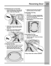
... reinsert. lb remove plate from left, pivot point Is down. Opening In ring should be on the tack 2 Remove trim ring cove' plate. Plug in dryer and cant nue operation. fine-thread, countersunk screws In upper snd lower holes 01 hinge side. 3 Install 2 short, course-Thread, panhead screws through lace of...
... reinsert. lb remove plate from left, pivot point Is down. Opening In ring should be on the tack 2 Remove trim ring cove' plate. Plug in dryer and cant nue operation. fine-thread, countersunk screws In upper snd lower holes 01 hinge side. 3 Install 2 short, course-Thread, panhead screws through lace of...


