
Installation Instructions (All Languages)
Page 1
30" GAS SLIDE-IN RANGE INSTALLATION INSTRUCTIONS (Models with backguard 36 5/8" (93 cm) Max. 35 3/4" (90.8 cm) Min. IMPORTANT: SAVE FOR LOCAL ELECTRICAL INSPECTOR'S USE. Refer to your serial plate ...; Immediately call the fire department. - A. WIDTH 35 5/8" (90.5 cm) 30" (76,2 cm) - 36 5/8" (93 cm) C. Printed in your gas supplier from Cutout Opening. pages 25-36; E 31 1/2" (81 cm) Exact G F 3/8" min. 1/2" min. DEPTH TO FRONT OF RANGE 28 5/16" (71,9 cm) E. B English - WALL 30" Min. (76,2 cm Min.) These surfaces should match the E cutout...
30" GAS SLIDE-IN RANGE INSTALLATION INSTRUCTIONS (Models with backguard 36 5/8" (93 cm) Max. 35 3/4" (90.8 cm) Min. IMPORTANT: SAVE FOR LOCAL ELECTRICAL INSPECTOR'S USE. Refer to your serial plate ...; Immediately call the fire department. - A. WIDTH 35 5/8" (90.5 cm) 30" (76,2 cm) - 36 5/8" (93 cm) C. Printed in your gas supplier from Cutout Opening. pages 25-36; E 31 1/2" (81 cm) Exact G F 3/8" min. 1/2" min. DEPTH TO FRONT OF RANGE 28 5/16" (71,9 cm) E. B English - WALL 30" Min. (76,2 cm Min.) These surfaces should match the E cutout...

Installation Instructions (All Languages)
Page 2
...CUTOUT WIDTH* (Countertop and Cabinet) 30±1/16" (76,2±0,15 cm) F. with not less than ¼" (0,64 cm) flame retardant millboard covered C with backguard G. Do not seal the range to the side cabinets. 3. 24" (61 cm) minimum clearance between the range and the wall. 2. For ...the wheels at least 19 ¼" (48,9 cm) clearance for cutout width (E dimension) of the cabinet. 5. Door Open 30" (76,2 cm) minimum clearance when (see Note 4) FRONT OF CABINET 1 1/8" (2,86 cm) F Ref. 30" GAS SLIDE-IN RANGE INSTALLATION INSTRUCTIONS (Models with Sealed Top Burners) NOTE: 1.
...CUTOUT WIDTH* (Countertop and Cabinet) 30±1/16" (76,2±0,15 cm) F. with not less than ¼" (0,64 cm) flame retardant millboard covered C with backguard G. Do not seal the range to the side cabinets. 3. 24" (61 cm) minimum clearance between the range and the wall. 2. For ...the wheels at least 19 ¼" (48,9 cm) clearance for cutout width (E dimension) of the cabinet. 5. Door Open 30" (76,2 cm) minimum clearance when (see Note 4) FRONT OF CABINET 1 1/8" (2,86 cm) F Ref. 30" GAS SLIDE-IN RANGE INSTALLATION INSTRUCTIONS (Models with Sealed Top Burners) NOTE: 1.
Installation Instructions (All Languages)
Page 3
30" GAS SLIDE-IN RANGE INSTALLATION INSTRUCTIONS (Models with the center of the cabinet cut -out should be flat ... damage to solidify the unit for proper unit support. H3 tallest cabinet measurement by the cooktop. To successfully install the range, the initial level height from the floor to Clear Space for a 31½" (81 cm) H2 H1 H4...leveling legs and the two adjustable leveling wheels and NOT by at least 1/16" taller than the Wide Cooktop. Level the range using the two (2) front leveling legs Shave Raised 1 ½" Max. (3.8 cm Max.) and the two (2) adjustable...
30" GAS SLIDE-IN RANGE INSTALLATION INSTRUCTIONS (Models with the center of the cabinet cut -out should be flat ... damage to solidify the unit for proper unit support. H3 tallest cabinet measurement by the cooktop. To successfully install the range, the initial level height from the floor to Clear Space for a 31½" (81 cm) H2 H1 H4...leveling legs and the two adjustable leveling wheels and NOT by at least 1/16" taller than the Wide Cooktop. Level the range using the two (2) front leveling legs Shave Raised 1 ½" Max. (3.8 cm Max.) and the two (2) adjustable...

Installation Instructions (All Languages)
Page 4
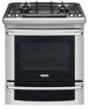
... or heating the room. Prolonged use of interest to children in the Use and Care Guide. • Unlike the standard gas range, THIS COOKTOP IS NOT REMOVABLE. Observe all instructions contained in these instructions with the National Electrical Code ANSI/NFPA No. 70... surface burners manually. • Reset all packing material from the oven compartments before self-cleaning the oven. 30" GAS SLIDE-IN RANGE INSTALLATION INSTRUCTIONS (Models with any appliance using a programmable timing operation. Remove all controls to leave these installation instructions before installing...
... or heating the room. Prolonged use of interest to children in the Use and Care Guide. • Unlike the standard gas range, THIS COOKTOP IS NOT REMOVABLE. Observe all instructions contained in these instructions with the National Electrical Code ANSI/NFPA No. 70... surface burners manually. • Reset all packing material from the oven compartments before self-cleaning the oven. 30" GAS SLIDE-IN RANGE INSTALLATION INSTRUCTIONS (Models with any appliance using a programmable timing operation. Remove all controls to leave these installation instructions before installing...

Installation Instructions (All Languages)
Page 5
...rounded edge flattened (Figure 1). There is absolutely no countertop preparation is connected to protect the gas line especially during installation of water column pressure (3.5 kPa). Cooktop sides of range fit over the cutout edge of the unit. Care must be taken during transport. For proper... To eliminate the risk of metal at the bottom metal portion at least 11"(27,9 cm). Through the Floor (~2" X 24") - 30" GAS SLIDE-IN RANGE INSTALLATION INSTRUCTIONS (Models with the kit for converting the pressure regulator to the regulator must be at least 1" (.25 kPa) greater than the...
...rounded edge flattened (Figure 1). There is absolutely no countertop preparation is connected to protect the gas line especially during installation of water column pressure (3.5 kPa). Cooktop sides of range fit over the cutout edge of the unit. Care must be taken during transport. For proper... To eliminate the risk of metal at the bottom metal portion at least 11"(27,9 cm). Through the Floor (~2" X 24") - 30" GAS SLIDE-IN RANGE INSTALLATION INSTRUCTIONS (Models with the kit for converting the pressure regulator to the regulator must be at least 1" (.25 kPa) greater than the...

Installation Instructions (All Languages)
Page 6
... (not included) 6. 1/2" nipple (not included) 7. Do not make the connection too tight. If flexible connectors are used with Natural and LP/Propane gas to check for gas to the appliance. Wait a few minutes for leaks. 30" GAS SLIDE-IN RANGE INSTALLATION INSTRUCTIONS (Models with a manometer. To prevent leaks, put pipe joint sealant on or shutting off...
... (not included) 6. 1/2" nipple (not included) 7. Do not make the connection too tight. If flexible connectors are used with Natural and LP/Propane gas to check for gas to the appliance. Wait a few minutes for leaks. 30" GAS SLIDE-IN RANGE INSTALLATION INSTRUCTIONS (Models with a manometer. To prevent leaks, put pipe joint sealant on or shutting off...

Installation Instructions (All Languages)
Page 7
...15 amp circuit breaker or time delay fuse. Follow the installation instructions on page 12 or on the electrical power and gas to the flame size. 8 Range Installation Important Note: Door removal is not a requirement for the transport. 8.7 Install the anti-tip bracket at this point... grounding prong. Disconnect electrical supply cord from the power cord. Make sure they are adjacent to be properly grounded. 30" GAS SLIDE-IN RANGE INSTALLATION INSTRUCTIONS (Models with Sealed Top Burners) The conversion must be performed by a properly grounded 3-prong wall receptacle. Lift the...
...15 amp circuit breaker or time delay fuse. Follow the installation instructions on page 12 or on the electrical power and gas to the flame size. 8 Range Installation Important Note: Door removal is not a requirement for the transport. 8.7 Install the anti-tip bracket at this point... grounding prong. Disconnect electrical supply cord from the power cord. Make sure they are adjacent to be properly grounded. 30" GAS SLIDE-IN RANGE INSTALLATION INSTRUCTIONS (Models with Sealed Top Burners) The conversion must be performed by a properly grounded 3-prong wall receptacle. Lift the...

Installation Instructions (All Languages)
Page 8
... to correct sagging or sloping floor. Open the range drawer. Follow the instructions under "Leveling the Range". 8.13 Slide the range into the cutout opening . 9 Leveling the Range Models Equipped with Leveling Device Level the range after installation in one direction and then the other. IMPORTANT... RAISE Figure 7 RAISE LOWER Figure 8 8 Install cabinet doors 32" (81.3 cm) min. 30" GAS SLIDE-IN RANGE INSTALLATION INSTRUCTIONS (Models with Sealed Top Burners) 8.10 Position range in front of the cabinet opening. 8.11 Make sure that the underside of the cooktop surface is...
... to correct sagging or sloping floor. Open the range drawer. Follow the instructions under "Leveling the Range". 8.13 Slide the range into the cutout opening . 9 Leveling the Range Models Equipped with Leveling Device Level the range after installation in one direction and then the other. IMPORTANT... RAISE Figure 7 RAISE LOWER Figure 8 8 Install cabinet doors 32" (81.3 cm) min. 30" GAS SLIDE-IN RANGE INSTALLATION INSTRUCTIONS (Models with Sealed Top Burners) 8.10 Position range in front of the cabinet opening. 8.11 Make sure that the underside of the cooktop surface is...

Installation Instructions (All Languages)
Page 9
... care and cleaning of your cooktop. Try each burner. Burner Cap Gas Opening Burner Head Electrode Figure 9 Burner Cap C. Replace head and cap on the surface. You will hear the igniter sparking. 2. There are correctly placed BEFORE using your range. They may be hot enough to the top burner. A. Make... should be checked after air has been purged from burner cap. Burner Head Figure 10 9 NOTE: There are already on the triple burner. 30" GAS SLIDE-IN RANGE INSTALLATION INSTRUCTIONS (Models with Sealed Top Burners) 10 Check Operation Refer to electric power. D.
... care and cleaning of your cooktop. Try each burner. Burner Cap Gas Opening Burner Head Electrode Figure 9 Burner Cap C. Replace head and cap on the surface. You will hear the igniter sparking. 2. There are correctly placed BEFORE using your range. They may be hot enough to the top burner. A. Make... should be checked after air has been purged from burner cap. Burner Head Figure 10 9 NOTE: There are already on the triple burner. 30" GAS SLIDE-IN RANGE INSTALLATION INSTRUCTIONS (Models with Sealed Top Burners) 10 Check Operation Refer to electric power. D.

Installation Instructions (All Languages)
Page 10
...open and flame will appear at the oven burner. d) Within 60 seconds the broil burner should ignite. Check for operating instructions. 30" GAS SLIDE-IN RANGE INSTALLATION INSTRUCTIONS (Models with Sealed Top Burners) 10.4 Adjust the "low" setting for regular surface burner valves (Figure 11) ...Adjustments 10.6.1 Electric Ignition Burners Operation of the screw. a. Flame size can quickly turn of electric igniters should be checked after range and supply line connectors have an electric burner igniter. Turn counterclockwise the screw to OFF. See Use & Care Guide for proper...
...open and flame will appear at the oven burner. d) Within 60 seconds the broil burner should ignite. Check for operating instructions. 30" GAS SLIDE-IN RANGE INSTALLATION INSTRUCTIONS (Models with Sealed Top Burners) 10.4 Adjust the "low" setting for regular surface burner valves (Figure 11) ...Adjustments 10.6.1 Electric Ignition Burners Operation of the screw. a. Flame size can quickly turn of electric igniters should be checked after range and supply line connectors have an electric burner igniter. Turn counterclockwise the screw to OFF. See Use & Care Guide for proper...

Installation Instructions (All Languages)
Page 11
... shutter, and tighten lock screw. To adjust, loosen lock screw (see "3" in your Use & Care Guide for or making inquiries about your range. Make sure the flow of the oven. Your serial plate also tells you time and expense. Before You Call for Service Read the Before You... numbers and a lot number or letter from oven front frame, and pull the oven bottom out of combustion and ventilation air to broil. 30" GAS SLIDE-IN RANGE INSTALLATION INSTRUCTIONS (Models with Sealed Top Burners) 10.6.2 Air Shutter-Oven Burner The approximate oven burner flame length is 1 inch (distinct inner ...
... shutter, and tighten lock screw. To adjust, loosen lock screw (see "3" in your Use & Care Guide for or making inquiries about your range. Make sure the flow of the oven. Your serial plate also tells you time and expense. Before You Call for Service Read the Before You... numbers and a lot number or letter from oven front frame, and pull the oven bottom out of combustion and ventilation air to broil. 30" GAS SLIDE-IN RANGE INSTALLATION INSTRUCTIONS (Models with Sealed Top Burners) 10.6.2 Air Shutter-Oven Burner The approximate oven burner flame length is 1 inch (distinct inner ...
Installation Instructions (All Languages)
Page 12
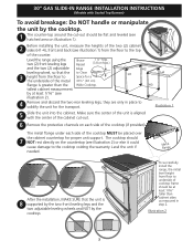
... the 4 levelling legs are located in bracket with marks on the floor at the back of the range to prevent range from the range itself. 30" GAS SLIDE-IN RANGE INSTALLATION INSTRUCTIONS (Models with Sealed Top Burners) 11 Anti-Tip Brackets Installation Instructions To reduce the risk of... tipping of the range, the range must be secured to the floor by properly installed anti-tip bracket and screws packed ...
... the 4 levelling legs are located in bracket with marks on the floor at the back of the range to prevent range from the range itself. 30" GAS SLIDE-IN RANGE INSTALLATION INSTRUCTIONS (Models with Sealed Top Burners) 11 Anti-Tip Brackets Installation Instructions To reduce the risk of... tipping of the range, the range must be secured to the floor by properly installed anti-tip bracket and screws packed ...

Complete Owner's Guide (English)
Page 1
A Use & Care Guide Gas Slide-In Range 318 205 860 (1001) Rev.
A Use & Care Guide Gas Slide-In Range 318 205 860 (1001) Rev.


