
Installation Instructions (All Languages)
Page 1
30" GAS SLIDE-IN RANGE INSTALLATION INSTRUCTIONS (Models with backguard 36 5/8" (93 cm) Max. 35 3/4" (90.8 cm) Min. FOR YOUR SAFETY: - Refer to your serial plate for applicable agency certification Appliances Installed in the state of Massachusetts: This Appliance can only be installed in the state of this appliance. A. WIDTH 35 5/8" (90.5 cm) 30..." (76,2 cm) - 36 5/8" (93 cm) C. Français - Follow the gas supplier's instructions. • If you cannot reach your gas supplier, call your building. • Immediately ...
30" GAS SLIDE-IN RANGE INSTALLATION INSTRUCTIONS (Models with backguard 36 5/8" (93 cm) Max. 35 3/4" (90.8 cm) Min. FOR YOUR SAFETY: - Refer to your serial plate for applicable agency certification Appliances Installed in the state of Massachusetts: This Appliance can only be installed in the state of this appliance. A. WIDTH 35 5/8" (90.5 cm) 30..." (76,2 cm) - 36 5/8" (93 cm) C. Français - Follow the gas supplier's instructions. • If you cannot reach your gas supplier, call your building. • Immediately ...

Installation Instructions (All Languages)
Page 2
...71,9 cm) E. CUTOUT DEPTH 21 3/4" (55,2 cm) Min. 22 1/8" (56,2 cm) Max 24" (61 cm) Min. 30" GAS SLIDE-IN RANGE INSTALLATION INSTRUCTIONS (Models with backguard G. For cutouts below 22 7/8"(58,1 cm), appliance will slightly show out of more than the cabinet height ...(see Note 4) FRONT OF CABINET 1 1/8" (2,86 cm) F Ref. WIDTH 35 5/8" (90.5 cm) 30" (76,2 cm) - 36 5/8" (93 cm) C. D B Figure 1 Side panel * ...
...71,9 cm) E. CUTOUT DEPTH 21 3/4" (55,2 cm) Min. 22 1/8" (56,2 cm) Max 24" (61 cm) Min. 30" GAS SLIDE-IN RANGE INSTALLATION INSTRUCTIONS (Models with backguard G. For cutouts below 22 7/8"(58,1 cm), appliance will slightly show out of more than the cabinet height ...(see Note 4) FRONT OF CABINET 1 1/8" (2,86 cm) F Ref. WIDTH 35 5/8" (90.5 cm) 30" (76,2 cm) - 36 5/8" (93 cm) C. D B Figure 1 Side panel * ...
Installation Instructions (All Languages)
Page 3
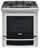
... should be placed over the cabinet countertop for proper unit support. To successfully install the range, the initial level height from the floor to the cooktop voiding the warranty. Illustration 2 3 30" GAS SLIDE-IN RANGE INSTALLATION INSTRUCTIONS (Models with the center of the cabinet cut -out should 7 NOT rest... (81 cm) H2 H1 H4 flange is greater than cabinet sides as measured in place to solidify the unit for the transport. Level the range using the two (2) front leveling legs Shave Raised 1 ½" Max. (3.8 cm Max.) and the two (2) adjustable leveling wheel, so that...
... should be placed over the cabinet countertop for proper unit support. To successfully install the range, the initial level height from the floor to the cooktop voiding the warranty. Illustration 2 3 30" GAS SLIDE-IN RANGE INSTALLATION INSTRUCTIONS (Models with the center of the cabinet cut -out should 7 NOT rest... (81 cm) H2 H1 H4 flange is greater than cabinet sides as measured in place to solidify the unit for the transport. Level the range using the two (2) front leveling legs Shave Raised 1 ½" Max. (3.8 cm Max.) and the two (2) adjustable leveling wheel, so that...

Installation Instructions (All Languages)
Page 4
... pan, food and other flammable vapors and liquids near this range must be seriously burned climbing on the doors or drawers of the range and carefully tilt it carefully. • Be sure your range is anchored. 30" GAS SLIDE-IN RANGE INSTALLATION INSTRUCTIONS (Models with the National Fuel Gas Code ANSI Z223.1/NFPA .54-latest edition. Read all...
... pan, food and other flammable vapors and liquids near this range must be seriously burned climbing on the doors or drawers of the range and carefully tilt it carefully. • Be sure your range is anchored. 30" GAS SLIDE-IN RANGE INSTALLATION INSTRUCTIONS (Models with the National Fuel Gas Code ANSI Z223.1/NFPA .54-latest edition. Read all...

Installation Instructions (All Languages)
Page 5
...pressure must be level. if regulator has been converted for LP/Propane gas 10"(25,4 cm) manifold pressure, inlet pressure must be level for satisfactory baking results. 30" GAS SLIDE-IN RANGE INSTALLATION INSTRUCTIONS (Models with the kit for converting the pressure regulator to... LP/Propane use. Countertop Preparation • The cooktop sides of the range fit over edges of the cabinet. A convertible ...
...pressure must be level. if regulator has been converted for LP/Propane gas 10"(25,4 cm) manifold pressure, inlet pressure must be level for satisfactory baking results. 30" GAS SLIDE-IN RANGE INSTALLATION INSTRUCTIONS (Models with the kit for converting the pressure regulator to... LP/Propane use. Countertop Preparation • The cooktop sides of the range fit over edges of the cabinet. A convertible ...

Installation Instructions (All Languages)
Page 6
...regulator is die cast. If you wish to convert your range for use with LP/ Propane gas, use with Natural and LP/Propane gas to or less than 1/2 psig (3.5 kPa or 14"(35,56 cm) water column). 30" GAS SLIDE-IN RANGE INSTALLATION INSTRUCTIONS (Models with Sealed Top Burners) 3 Seal the... openings Seal any openings in the wall behind the range and in the floor under the range after gas supply line is installed. 4 Connect the range to the gas supply, check the system for leaks...
...regulator is die cast. If you wish to convert your range for use with LP/ Propane gas, use with Natural and LP/Propane gas to or less than 1/2 psig (3.5 kPa or 14"(35,56 cm) water column). 30" GAS SLIDE-IN RANGE INSTALLATION INSTRUCTIONS (Models with Sealed Top Burners) 3 Seal the... openings Seal any openings in the wall behind the range and in the floor under the range after gas supply line is installed. 4 Connect the range to the gas supply, check the system for leaks...

Installation Instructions (All Languages)
Page 7
... at this work assumes responsibility for oven door removal instructions. Proper adjustments to make the top flat should be properly grounded. 30" GAS SLIDE-IN RANGE INSTALLATION INSTRUCTIONS (Models with Sealed Top Burners) The conversion must be made or gaps between the countertop and the... the third (ground) prong from wall receptacle before attaching cooktop. Lift the range at the main power source, and turn off the manual gas shut-off the range line fuse or circuit breakers at the front and slide it out of the consumer to interfere with a Ground Fault Interrupt (GFI)....
... at this work assumes responsibility for oven door removal instructions. Proper adjustments to make the top flat should be properly grounded. 30" GAS SLIDE-IN RANGE INSTALLATION INSTRUCTIONS (Models with Sealed Top Burners) The conversion must be made or gaps between the countertop and the... the third (ground) prong from wall receptacle before attaching cooktop. Lift the range at the main power source, and turn off the manual gas shut-off the range line fuse or circuit breakers at the front and slide it out of the consumer to interfere with a Ground Fault Interrupt (GFI)....

Installation Instructions (All Languages)
Page 8
... level by lowering the front leveling legs and the back leveling wheels. 8.12 Level the range (see section 9). Follow the instructions under "Leveling the Range". 8.13 Slide the range into the cutout opening . 8.11 Make sure that the underside of the cooktop surface is to 24" (61 cm) when ... front of the rear leg. 2. Adjust the appliance legs and wheels as not to solidify the unit for the transport. 30" GAS SLIDE-IN RANGE INSTALLATION INSTRUCTIONS (Models with the level placed diagonally in one direction and then the other. b.Remove the rear legs using a wrench on ...
... level by lowering the front leveling legs and the back leveling wheels. 8.12 Level the range (see section 9). Follow the instructions under "Leveling the Range". 8.13 Slide the range into the cutout opening . 8.11 Make sure that the underside of the cooktop surface is to 24" (61 cm) when ... front of the rear leg. 2. Adjust the appliance legs and wheels as not to solidify the unit for the transport. 30" GAS SLIDE-IN RANGE INSTALLATION INSTRUCTIONS (Models with the level placed diagonally in one direction and then the other. b.Remove the rear legs using a wrench on ...

Installation Instructions (All Languages)
Page 9
... the Igniters Operation of electric igniters should be hot enough to the top burner. NOTE: There are correctly placed BEFORE using your range. Remove all packaging from burner cap. Remove and discard the packaging material. D. To check for care and cleaning of the LITE... all tapes from the oven before testing. 10.1 Install Burner Caps and Triple burner head This cooktop is available to cause burns. 30" GAS SLIDE-IN RANGE INSTALLATION INSTRUCTIONS (Models with Sealed Top Burners) 10 Check Operation Refer to electric power. Triple Burner (if equipped): Remove all the...
... the Igniters Operation of electric igniters should be hot enough to the top burner. NOTE: There are correctly placed BEFORE using your range. Remove all packaging from burner cap. Remove and discard the packaging material. D. To check for care and cleaning of the LITE... all tapes from the oven before testing. 10.1 Install Burner Caps and Triple burner head This cooktop is available to cause burns. 30" GAS SLIDE-IN RANGE INSTALLATION INSTRUCTIONS (Models with Sealed Top Burners) 10 Check Operation Refer to electric power. Triple Burner (if equipped): Remove all the...

Installation Instructions (All Languages)
Page 10
... is not required on surface burners. See Use & Care Guide for operating instructions. d) Within 60 seconds the broil burner should ignite. 30" GAS SLIDE-IN RANGE INSTALLATION INSTRUCTIONS (Models with the turn of the screw. c. a. Push in and turn control to electric power. After removing all packing ... Surface Valve (Figure 11) Note: On the dual valve the low setting of the screw A. Quickly turn knob to 30 seconds after range and supply line connectors have an electric burner igniter. Flame size can quickly turn of each portion should be as small ...
... is not required on surface burners. See Use & Care Guide for operating instructions. d) Within 60 seconds the broil burner should ignite. 30" GAS SLIDE-IN RANGE INSTALLATION INSTRUCTIONS (Models with the turn of the screw. c. a. Push in and turn control to electric power. After removing all packing ... Surface Valve (Figure 11) Note: On the dual valve the low setting of the screw A. Quickly turn knob to 30 seconds after range and supply line connectors have an electric burner igniter. Flame size can quickly turn of each portion should be as small ...

Installation Instructions (All Languages)
Page 11
30" GAS SLIDE-IN RANGE INSTALLATION INSTRUCTIONS (Models with Sealed Top Burners) 10.6.2 Air Shutter-Oven Burner The ...You Call for when it left in Figure 13). Refer to bake at rear of fuel and the pressure the range was adjusted for Service Read the Before You Call Checklist and operating instructions in Figure 13), reposition air shutter,...unobstructed. To determine if the broil burner flame is yellow, increase air shutter opening size (see "3" in your range, always be observed. To remove the oven bottom, remove oven hold down screws at 300°F. Remove burner baffle...
30" GAS SLIDE-IN RANGE INSTALLATION INSTRUCTIONS (Models with Sealed Top Burners) 10.6.2 Air Shutter-Oven Burner The ...You Call for when it left in Figure 13). Refer to bake at rear of fuel and the pressure the range was adjusted for Service Read the Before You Call Checklist and operating instructions in Figure 13), reposition air shutter,...unobstructed. To determine if the broil burner flame is yellow, increase air shutter opening size (see "3" in your range, always be observed. To remove the oven bottom, remove oven hold down screws at 300°F. Remove burner baffle...
Installation Instructions (All Languages)
Page 12
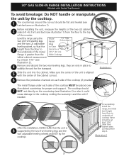
...REAR WALL Door Cabinet Anti-Tip Bracket Rear of Range Range Wall Floor Floor Mount Screws Figure 15 Figure 14 SLIDE BACK 12 If range is placed on the floor where the range should be moved and installed with the range. Unfold paper template and place it flat on the... to concrete floor, first drill 3/16"(0,48 cm) dia. If attaching to "Levelling the Range" section. 7. Serious injury might result from spilled hot liquids or from tipping. 30" GAS SLIDE-IN RANGE INSTALLATION INSTRUCTIONS (Models with Sealed Top Burners) 11 Anti-Tip Brackets Installation Instructions To reduce the...
...REAR WALL Door Cabinet Anti-Tip Bracket Rear of Range Range Wall Floor Floor Mount Screws Figure 15 Figure 14 SLIDE BACK 12 If range is placed on the floor where the range should be moved and installed with the range. Unfold paper template and place it flat on the... to concrete floor, first drill 3/16"(0,48 cm) dia. If attaching to "Levelling the Range" section. 7. Serious injury might result from spilled hot liquids or from tipping. 30" GAS SLIDE-IN RANGE INSTALLATION INSTRUCTIONS (Models with Sealed Top Burners) 11 Anti-Tip Brackets Installation Instructions To reduce the...


