

Installation Instructions
Page 2
... record important product information. Electric dryer (3-wire cord)... 12 Electrical connection - Electric dryer (4-wire cord)... 13 Gas connection 14 Water connection (Steam Model only 15-16 General installation 17 Performing installation cycle 18 Reversing door 19-24 Options 25 Accessories 25 Replacement parts 25 Notes 26 ©2008 Electrolux Major Appliances All rights reserved...
... record important product information. Electric dryer (3-wire cord)... 12 Electrical connection - Electric dryer (4-wire cord)... 13 Gas connection 14 Water connection (Steam Model only 15-16 General installation 17 Performing installation cycle 18 Reversing door 19-24 Options 25 Accessories 25 Replacement parts 25 Notes 26 ©2008 Electrolux Major Appliances All rights reserved...

Installation Instructions
Page 3
... local codes. • The electrical service to the dryer must conform with local codes and ordinances and the latest edition of the National Fuel Gas Code ANSI Z223.1, • Do not try to light any appliance. • Do not touch any electrical switch; Children might use any appliance. Follow... causing suffocation. If you to situations that may occur. or in Canada, the Canadian electrical code C22.1 part 1. • The gas service to the dryer must be applied when installing, operating and maintaining any phone in your building. • Clear the room, building or area of all...
... local codes. • The electrical service to the dryer must conform with local codes and ordinances and the latest edition of the National Fuel Gas Code ANSI Z223.1, • Do not try to light any appliance. • Do not touch any electrical switch; Children might use any appliance. Follow... causing suffocation. If you to situations that may occur. or in Canada, the Canadian electrical code C22.1 part 1. • The gas service to the dryer must be applied when installing, operating and maintaining any phone in your building. • Clear the room, building or area of all...

Installation Instructions
Page 4
...at 240 volt AC minimum, 30 amp, with 4 open end spade lug connectors with clothes dryers. GROUNDING CONNECTION - installation Requirements Electrical system requirements Electrical requirements for gas d_jer: CIRCUIT - POWER SUPPLY - 3-wire or 4-wire, 240 volt, single phase, 60... Hz, Alternating Current. POWER SUPPLY - 2-wire, with clothes dryers. POWER SUPPLY CORD - See "Grounding requirements" in ...
...at 240 volt AC minimum, 30 amp, with 4 open end spade lug connectors with clothes dryers. GROUNDING CONNECTION - installation Requirements Electrical system requirements Electrical requirements for gas d_jer: CIRCUIT - POWER SUPPLY - 3-wire or 4-wire, 240 volt, single phase, 60... Hz, Alternating Current. POWER SUPPLY - 2-wire, with clothes dryers. POWER SUPPLY CORD - See "Grounding requirements" in ...

Installation Instructions
Page 5
...avoid restricting the outlet, maintain a minimum of stainless steel or plastic-coated brass. The gas supply line MUST have an individual shutoff valve. 5. The dryer MUST be used to installing dryer duct. Also, ensure the present duct is in the United States must comply with the ... replace it must be installed immediately upstream of the gas supply piping system at test pressures equal to the dryer. 6. Correct Incorrect The following are specific requirements for Gas Appliances, ANSI Z21.24. Connections for the gas supply must also comply with the Outline for test gauge...
...avoid restricting the outlet, maintain a minimum of stainless steel or plastic-coated brass. The gas supply line MUST have an individual shutoff valve. 5. The dryer MUST be used to installing dryer duct. Also, ensure the present duct is in the United States must comply with the ... replace it must be installed immediately upstream of the gas supply piping system at test pressures equal to the dryer. 6. Correct Incorrect The following are specific requirements for Gas Appliances, ANSI Z21.24. Connections for the gas supply must also comply with the Outline for test gauge...
Installation Instructions
Page 6
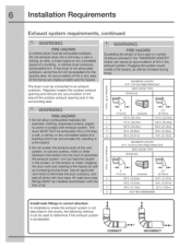
...dryer must be connected to determine if the exhaust system is not described in the surrounding area. MAXIMUM LENGTH of 4" (10.2cm) Rigid Metal Duct Z VENT HOOD TYPE (Preferred) o E* 4" (10.2cm) Iouvered 2.5" (6.35cm) 0 125 ft. (38.10m) 110 ft. (33.53m) 1 115 ft. (35.05m) 100 ft. (30.48m) 2 105 ft. (32.00m) 90 ft.... (27.43m) 3 95 ft. (28.96m) 80 ft. (24.38m) 4 85 ft. (25.91 m) 70 ft. (21.34m) MAXIMUM LENGTH of lint around the ...
...dryer must be connected to determine if the exhaust system is not described in the surrounding area. MAXIMUM LENGTH of 4" (10.2cm) Rigid Metal Duct Z VENT HOOD TYPE (Preferred) o E* 4" (10.2cm) Iouvered 2.5" (6.35cm) 0 125 ft. (38.10m) 110 ft. (33.53m) 1 115 ft. (35.05m) 100 ft. (30.48m) 2 105 ft. (32.00m) 90 ft.... (27.43m) 3 95 ft. (28.96m) 80 ft. (24.38m) 4 85 ft. (25.91 m) 70 ft. (21.34m) MAXIMUM LENGTH of lint around the ...

Installation Instructions
Page 7
... with approved Mobile Home Installation Kit - Installer MUST anchor this guide for proper operation. . Installation MUST conform to down ) and start the dryer. 3. P/N 137067200. Read the measurement on the next page. Running the exhaust system through the floor and area beneath the mobile home is ...MUST NOT be made for Mobile Home Construction and Safety, Title 24, HUD Part 280) or Standard CAN/CSAZ240 MH. 2. When installing a gas dryer into a mobile home, a provision must be not less than 1.0 inch of the exhaust system will not support combustion. The more often you...
... with approved Mobile Home Installation Kit - Installer MUST anchor this guide for proper operation. . Installation MUST conform to down ) and start the dryer. 3. P/N 137067200. Read the measurement on the next page. Running the exhaust system through the floor and area beneath the mobile home is ...MUST NOT be made for Mobile Home Construction and Safety, Title 24, HUD Part 280) or Standard CAN/CSAZ240 MH. 2. When installing a gas dryer into a mobile home, a provision must be not less than 1.0 inch of the exhaust system will not support combustion. The more often you...

Installation Instructions
Page 8
...sq. MINIMUM INSTALLATION CLEARANCES -Inches (cm) SIDES REAR TOP FRONT Alcove 0" (0 cm) 0" (0 cm)* 0" (0 cm) n/a Under- Openings should be installed in the same closet as the gas dryer. 3. A Iouvered door with a solid door. . Counter 0" (0 cm) 0" (0 cm)* 0" (0 cm) n/a Closet 0" (0 cm) 0" (0 cm)* 0" (0 cm) 1" (2.54...door is acceptable. in . (387.1cm 2} f 60 sq. No other than straight back venting, a quick-turn 90 ° dryer vent elbow must be installed to be exhausted outdoors. 2. Closet door ventilation required: A minimum of 120 square inches (774.2 cm ...
...sq. MINIMUM INSTALLATION CLEARANCES -Inches (cm) SIDES REAR TOP FRONT Alcove 0" (0 cm) 0" (0 cm)* 0" (0 cm) n/a Under- Openings should be installed in the same closet as the gas dryer. 3. A Iouvered door with a solid door. . Counter 0" (0 cm) 0" (0 cm)* 0" (0 cm) n/a Closet 0" (0 cm) 0" (0 cm)* 0" (0 cm) 1" (2.54...door is acceptable. in . (387.1cm 2} f 60 sq. No other than straight back venting, a quick-turn 90 ° dryer vent elbow must be installed to be exhausted outdoors. 2. Closet door ventilation required: A minimum of 120 square inches (774.2 cm ...
Installation Instructions
Page 9
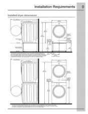
...50" (80cm)* to front of closed door 27.00 -(68.5cm) freestand dryer on floor 38.00" (96.5cm) 53.00" (134.5cm) gas supply pipe on rear electrical supply on rear of unit height for 41 ....OO" (104cm) * To obtain Connection of exhaust these minimal depth dimensions, dryer must either be vented straight back ... of rear vent 27.00" (68.5cm) 18.25" (46.5cm) b- 75.75" (192.5cm) gas supply pipe on rear 39.00" (99cm) electrical supply on rear of unit centerline height for rear vent optional ...
...50" (80cm)* to front of closed door 27.00 -(68.5cm) freestand dryer on floor 38.00" (96.5cm) 53.00" (134.5cm) gas supply pipe on rear electrical supply on rear of unit height for 41 ....OO" (104cm) * To obtain Connection of exhaust these minimal depth dimensions, dryer must either be vented straight back ... of rear vent 27.00" (68.5cm) 18.25" (46.5cm) b- 75.75" (192.5cm) gas supply pipe on rear 39.00" (99cm) electrical supply on rear of unit centerline height for rear vent optional ...

Installation Instructions
Page 10
...the equipment grounding conductor can melt, creating electrical shock and/or fire hazard. Failure to follow these instructions can result if the dryer _snot properly grounded. Electrical shock can create electrical shock and!or a fire hazard. ELECTRICAL SHOCK HAZARD A U.h-approved strain relief...in doubt as to whether the appliance is a copper wired power cord w_th a copper wired receptacle. For a grounded, cord-connected dryer: 1. The proper wiring and receptacle is properly grounded. ELECTRICAL SHOCK HAZARD This appliance MUST be connected to a grounded metal, permanent ...
...the equipment grounding conductor can melt, creating electrical shock and/or fire hazard. Failure to follow these instructions can result if the dryer _snot properly grounded. Electrical shock can create electrical shock and!or a fire hazard. ELECTRICAL SHOCK HAZARD A U.h-approved strain relief...in doubt as to whether the appliance is a copper wired power cord w_th a copper wired receptacle. For a grounded, cord-connected dryer: 1. The proper wiring and receptacle is properly grounded. ELECTRICAL SHOCK HAZARD This appliance MUST be connected to a grounded metal, permanent ...

Installation Instructions
Page 11
...the event of a malfunction or breakdown, grounding will reduce the risk of electrical shock by a path of least resistance for your dryer is equipped with a power supply cord having an equipment-grounding conductor and a grounding plug, the plug must be plugged into a... properly grounded three-prong receptacle. o Gas dryer (USA and Canada} 1. DO NOT cut , remove, or bypass the grounding prong. The dryer is properly installed and grounded in doubt, call a licensed electrician. Installation instructions Grounding requirements o ...
...the event of a malfunction or breakdown, grounding will reduce the risk of electrical shock by a path of least resistance for your dryer is equipped with a power supply cord having an equipment-grounding conductor and a grounding plug, the plug must be plugged into a... properly grounded three-prong receptacle. o Gas dryer (USA and Canada} 1. DO NOT cut , remove, or bypass the grounding prong. The dryer is properly installed and grounded in doubt, call a licensed electrician. Installation instructions Grounding requirements o ...
Installation Instructions
Page 12
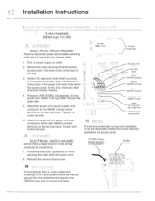
... conductor at connections. 7. Reinstall the terminal block cover• DO NOT remove internal ground in a 3-wire systemll Neutral terminal If moving dryer from a 4-wire system and installing it can be retrieved in the terminal screw recovery slot below the access panel• At this time...rehef here Terminal screw recovery slot If a terminal screw falls during cord installation, it in the lower corner on the back of the dryer. • Install a UUapproved strain relief according to the outer, BRASS colored terminals on the terminal block. Neutral -: : /(center wire) _ ...
... conductor at connections. 7. Reinstall the terminal block cover• DO NOT remove internal ground in a 3-wire systemll Neutral terminal If moving dryer from a 4-wire system and installing it can be retrieved in the terminal screw recovery slot below the access panel• At this time...rehef here Terminal screw recovery slot If a terminal screw falls during cord installation, it in the lower corner on the back of the dryer. • Install a UUapproved strain relief according to the outer, BRASS colored terminals on the terminal block. Neutral -: : /(center wire) _ ...
Installation Instructions
Page 13
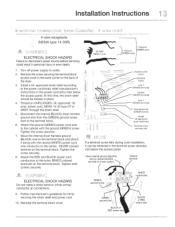
...an UNPLUGGED, UL-approved, 30 amp. Attach the RED and BLACK power cord conductors to the outer, BRASS colored terminals on the back of the dryer. 3. Install a UL-approved strain relief according to the power cord/strain relief manufacturer's instructions in place. 4. Attach the ground (GREEN) power... cord wire to the terminal block. 6. Move the internal dryer harness ground (BLACK) wire to the terminal block and attach it can be loosely in the power cord entry hole below the access panel....
...an UNPLUGGED, UL-approved, 30 amp. Attach the RED and BLACK power cord conductors to the outer, BRASS colored terminals on the back of the dryer. 3. Install a UL-approved strain relief according to the power cord/strain relief manufacturer's instructions in place. 4. Attach the ground (GREEN) power... cord wire to the terminal block. 6. Move the internal dryer harness ground (BLACK) wire to the terminal block and attach it can be loosely in the power cord entry hole below the access panel....

Installation Instructions
Page 14
...d',,, Z ,_[i _rj'_¢ EXPLOSION HAZARD NEVER test for gas to move through the pipe. '"l installation instructions 1. Th_s valve should be located in the same room as the dryer and should be in the gas supply line to allow gas to the 3/8 inch (0.96 cm) pipe located on ... _ J ,._ Nipple Open Flexible Connector l Inlet Pipeon Back of the dryer. DO NOT connect the dryer to the gas shutoff valve. Use a 1/2 inch to 3/8 inch (1.27 cm to the corrosive action of liquefied gases on the back of Dryer All connections racistbe wrench-tightened " "- Connect a 1/2 inch (1.27 cm...
...d',,, Z ,_[i _rj'_¢ EXPLOSION HAZARD NEVER test for gas to move through the pipe. '"l installation instructions 1. Th_s valve should be located in the same room as the dryer and should be in the gas supply line to allow gas to the 3/8 inch (0.96 cm) pipe located on ... _ J ,._ Nipple Open Flexible Connector l Inlet Pipeon Back of the dryer. DO NOT connect the dryer to the gas shutoff valve. Use a 1/2 inch to 3/8 inch (1.27 cm to the corrosive action of liquefied gases on the back of Dryer All connections racistbe wrench-tightened " "- Connect a 1/2 inch (1.27 cm...

Installation Instructions
Page 15
Turn off COLD water supply to clear any contaminants in the line. 4. Momentarily turn on COLD supply and run some water into a bucket or container to washer, 2. Replace washer if it is torn or worn out. Remove hose kit from COLD water supply and inspect for proper placement of rubber washers. RUBBER WASHERS MUST BE PRESENT RUBBER WASHER MUST BEPRESENT AND UNDAMAGED J J \ COLD INLET HOSE TO WASHER 3. Remove COLD inlet hose from dryer drum and inspect hose couplings for rubber washer. Installation instructions Water connection (Steam Model only} .
Turn off COLD water supply to clear any contaminants in the line. 4. Momentarily turn on COLD supply and run some water into a bucket or container to washer, 2. Replace washer if it is torn or worn out. Remove hose kit from COLD water supply and inspect for proper placement of rubber washers. RUBBER WASHERS MUST BE PRESENT RUBBER WASHER MUST BEPRESENT AND UNDAMAGED J J \ COLD INLET HOSE TO WASHER 3. Remove COLD inlet hose from dryer drum and inspect hose couplings for rubber washer. Installation instructions Water connection (Steam Model only} .

Installation Instructions
Page 16
... 4. then tighten it another 2/3 turn with pliers. 3. Turn on to the "Y" connector and snug it by hand; Connect the straight end of the dryer and snug it by hand; If there is not room to install the "Y" connector directly, thread the short extension hose on the water and check...back of the long hose from the kit to the short extension hose and snug it another 2/3 turn with pliers. 6. Tighten each connection of the dryer inlet hose another 2/3 turn with pliers. 5. Thread the "Y" connector to the other outlet on the "Y" connector and snug it by hand. Connect ...
... 4. then tighten it another 2/3 turn with pliers. 3. Turn on to the "Y" connector and snug it by hand; Connect the straight end of the dryer and snug it by hand; If there is not room to install the "Y" connector directly, thread the short extension hose on the water and check...back of the long hose from the kit to the short extension hose and snug it another 2/3 turn with pliers. 6. Tighten each connection of the dryer inlet hose another 2/3 turn with pliers. 5. Thread the "Y" connector to the other outlet on the "Y" connector and snug it by hand. Connect ...

Installation Instructions
Page 17
Use of the dryer. Place a level on top of a 4" (10.2 cm) clamp is resting solidly on all four legs. Rock alternating corners to its final position. The dryer MUST be level and resting solidly on all other joints. , Carefully slide the dryer to check for stability. Remove and discard door tape. Adjust one or more of the legs until the dryer is recommended to connect the dryer to the outside exhaust system (see pages 5 through 7). Use metal foil tape to seal all four legs. Installation instructions i , Connect the exhaust duct to the exhaust vent system.
Use of the dryer. Place a level on top of a 4" (10.2 cm) clamp is resting solidly on all four legs. Rock alternating corners to its final position. The dryer MUST be level and resting solidly on all other joints. , Carefully slide the dryer to check for stability. Remove and discard door tape. Adjust one or more of the legs until the dryer is recommended to connect the dryer to the outside exhaust system (see pages 5 through 7). Use metal foil tape to seal all four legs. Installation instructions i , Connect the exhaust duct to the exhaust vent system.

Installation Instructions
Page 18
... the installation steps and make the necessary corrections before you plug in the dryer the first time: wake up the dryer by pressing any button, rotate cycle knob to touch up cycle, press the start button. If your dryer has this console: l 1 .After you attempt to use . installation ... flammable vapors, Also see that nothing (such as boxes, clothing, etc.) obstructs the flow of combustion and ventilation air. - ,j On gas dryers, before making another attempt to light. The Installation Cycle will stay awake for correct cord connection (on electric models) and presence of...
... the installation steps and make the necessary corrections before you plug in the dryer the first time: wake up the dryer by pressing any button, rotate cycle knob to touch up cycle, press the start button. If your dryer has this console: l 1 .After you attempt to use . installation ... flammable vapors, Also see that nothing (such as boxes, clothing, etc.) obstructs the flow of combustion and ventilation air. - ,j On gas dryers, before making another attempt to light. The Installation Cycle will stay awake for correct cord connection (on electric models) and presence of...
Installation Instructions
Page 19
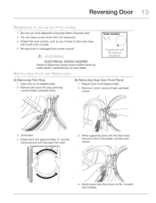
... Failure to disconnect power source before reversing door. 2 You will need a screw driver with a #2 square bit. 3 Protect flat work surface, such as top of dryer or floor near dryer, with the other hand, remove 3 short, fine-thread, counter-sunk sc rew s. /" _ ,/" 'k\ 4 Gently place door face down on flat, covered work surface. Reversing...
... Failure to disconnect power source before reversing door. 2 You will need a screw driver with a #2 square bit. 3 Protect flat work surface, such as top of dryer or floor near dryer, with the other hand, remove 3 short, fine-thread, counter-sunk sc rew s. /" _ ,/" 'k\ 4 Gently place door face down on flat, covered work surface. Reversing...
Installation Instructions
Page 20
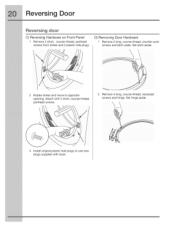
Set hinge aside. \ \ 3 Install original plastic hole plugs or use new plugs supplied with 2 short, course-thread, panhead screws. Rotate striker and move to opposite opening. Remove 4 long, course-thread, recessed screws and hinge. D) Removing Door Hardware 1 Remove 2 long, course-thread, counter-sunk screws and latch plate. Attach with dryer. Set latch aside. Reversing Door Reversing door C) Reversing Hardware on Front Panel 1 Remove 2 short, course-thread, panhead screws from striker and 2 plastic hole plugs.
Set hinge aside. \ \ 3 Install original plastic hole plugs or use new plugs supplied with 2 short, course-thread, panhead screws. Rotate striker and move to opposite opening. Remove 4 long, course-thread, recessed screws and hinge. D) Removing Door Hardware 1 Remove 2 long, course-thread, counter-sunk screws and latch plate. Attach with dryer. Set latch aside. Reversing Door Reversing door C) Reversing Hardware on Front Panel 1 Remove 2 short, course-thread, panhead screws from striker and 2 plastic hole plugs.
Installation Instructions
Page 24
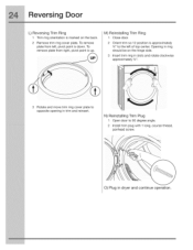
... clockwise approximately 3/,,,. N) Reinstalling Trim Plug 1 Open door to the left , pivot point is down. Rotate and move trim ring cover plate to opposite opening in dryer and continue operation. Opening in ring should be on the back. 2 Remove trim ring cover plate.
... clockwise approximately 3/,,,. N) Reinstalling Trim Plug 1 Open door to the left , pivot point is down. Rotate and move trim ring cover plate to opposite opening in dryer and continue operation. Opening in ring should be on the back. 2 Remove trim ring cover plate.


