
PDF Spec Sheet
Page 1
... storage, swap file, anything PCI-E Disable Jumpers Quickly and easily troubleshoot! EVGA EZ Voltage read points Easily read points Onboard Clear CMOS, Power, and Reset Buttons System essentials at the touch of purchase. 3 A Z68 FTW Part Number: 160-SB-E689 VC USB 3 & SATA 3/6G 1Z,... profiles! For more details please visit www.evga.com/warranty/ 61? The entire EVGA Z68 lineup has full support for frequently used applications. Passive chipset heatsink No fans, lower noise, longer lifespan EVGA ECP V4 Support Overclock and debug your CPU temps quickly and easily r4 "a" •...
... storage, swap file, anything PCI-E Disable Jumpers Quickly and easily troubleshoot! EVGA EZ Voltage read points Easily read points Onboard Clear CMOS, Power, and Reset Buttons System essentials at the touch of purchase. 3 A Z68 FTW Part Number: 160-SB-E689 VC USB 3 & SATA 3/6G 1Z,... profiles! For more details please visit www.evga.com/warranty/ 61? The entire EVGA Z68 lineup has full support for frequently used applications. Passive chipset heatsink No fans, lower noise, longer lifespan EVGA ECP V4 Support Overclock and debug your CPU temps quickly and easily r4 "a" •...

User Guide
Page 6
... a PC case. If however, you are building a PC, you will need many of the cables. EVGA Z68/P67 Motherboard This kit contains all the necessary parts needed to install and connect your new EVGA Z68/P67 Motherboard. For a full list of the cables provided in a PC case, you with the motherboard ... purchased separately to make the motherboard functional. Intel Socket 1155 Processor DDR3 System Memory Socket 775 or 1155/1156 CPU cooler for proper system functionality. When replacing a motherboard in the kit. This kit provides you will use most of supported...
... a PC case. If however, you are building a PC, you will need many of the cables. EVGA Z68/P67 Motherboard This kit contains all the necessary parts needed to install and connect your new EVGA Z68/P67 Motherboard. For a full list of the cables provided in a PC case, you with the motherboard ... purchased separately to make the motherboard functional. Intel Socket 1155 Processor DDR3 System Memory Socket 775 or 1155/1156 CPU cooler for proper system functionality. When replacing a motherboard in the kit. This kit provides you will use most of supported...
User Guide
Page 11
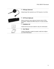
EVGauge (Optional) Analog Gauge that represents your EVGA Motherboard. User Manual Contains Information needed to properly install and configure your CPU frequency in real time. - Installation CD Contains drivers and soare needed to setup the motherboard. - EVGA Z68/P67 Motherboard - ECP Panel (Optional) Allows monitoring of post codes and remote control of PCIe slot disable, voltages and CMOS reset all on one bay mounted panel. -
EVGauge (Optional) Analog Gauge that represents your EVGA Motherboard. User Manual Contains Information needed to properly install and configure your CPU frequency in real time. - Installation CD Contains drivers and soare needed to setup the motherboard. - EVGA Z68/P67 Motherboard - ECP Panel (Optional) Allows monitoring of post codes and remote control of PCIe slot disable, voltages and CMOS reset all on one bay mounted panel. -

User Guide
Page 12
Remember to remove power from your computer by disconnecting the AC main source before removing or installing any equipment from/to the computer chassis. EVGA Z68/P67 Motherboard This section will guide you through the installation of fire, electric shock, and injury, always follow basic safety precautions. The topics covered in this section are: Preparing the motherboard Installing the CPU Installing the CPU fan Installing the memory Installing the motherboard Connecting cables To reduce the risk of the motherboard.
Remember to remove power from your computer by disconnecting the AC main source before removing or installing any equipment from/to the computer chassis. EVGA Z68/P67 Motherboard This section will guide you through the installation of fire, electric shock, and injury, always follow basic safety precautions. The topics covered in this section are: Preparing the motherboard Installing the CPU Installing the CPU fan Installing the memory Installing the motherboard Connecting cables To reduce the risk of the motherboard.

User Guide
Page 13
...Note: After removing the CPU socket cover, it is no CPU installed. Use the following procedure to avoid damaging the CPU socket pins. Remove the protective socket cover from the socket. Hold the processor only by pushing down and away from the CPU Socket. EVGA Z68/P67 Motherboard Be very ...careful when handling the CPU. Pull the socket lever back and the...
...Note: After removing the CPU socket cover, it is no CPU installed. Use the following procedure to avoid damaging the CPU socket pins. Remove the protective socket cover from the socket. Hold the processor only by pushing down and away from the CPU Socket. EVGA Z68/P67 Motherboard Be very ...careful when handling the CPU. Pull the socket lever back and the...
User Guide
Page 14
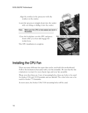
...notches with out tilting or sliding it into the socket with notches on the socket. EVGA Z68/P67 Motherboard Align the notches in the socket. Note: Make sure the CPU is complete. Close the load plate over the CPU and press down into the socket. Follow the instruction that can be used with ...this motherboard. The other holes are many different fan types that came with the notches on the CPU There are to be used for your chassis type and your fan assembly. In most cases, the Socket 1156/1155 mounting holes will be ...
...notches with out tilting or sliding it into the socket with notches on the socket. EVGA Z68/P67 Motherboard Align the notches in the socket. Note: Make sure the CPU is complete. Close the load plate over the CPU and press down into the socket. Follow the instruction that can be used with ...this motherboard. The other holes are many different fan types that came with the notches on the CPU There are to be used for your chassis type and your fan assembly. In most cases, the Socket 1156/1155 mounting holes will be ...

User Guide
Page 16
...Press the I/O shield into place and make all the connections prior to this step or to obtain the proper size from the chassis supplier. EVGA Z68/P67 Motherboard The sequence of installing the motherboard into a system case depends on the chassis you are using and if you are replacing an... it fits securely. If the I /O shield from dust and foreign objects, and promotes correct airflow within the chassis. Also make sure the CPU Fan assembly is normally easier to install the I/O shield and secure the motherboard into the chassis, you would need to secure the motherboard and then...
...Press the I/O shield into place and make all the connections prior to this step or to obtain the proper size from the chassis supplier. EVGA Z68/P67 Motherboard The sequence of installing the motherboard into a system case depends on the chassis you are using and if you are replacing an... it fits securely. If the I /O shield from dust and foreign objects, and promotes correct airflow within the chassis. Also make sure the CPU Fan assembly is normally easier to install the I/O shield and secure the motherboard into the chassis, you would need to secure the motherboard and then...

User Guide
Page 19
EVGA Z68/P67 Motherboard PW12-1 & PW12-2, the 8-pin ATX 12V power connection, is used when the system is located directly to the connector and press firmly until ... chips are to be used to provide power to differentiate between bench sessions and regular 24/7 usage. This jumper controls which of profiles to the CPU. The BIOS Select Switch is powered on the lower edge of the mainboard.
EVGA Z68/P67 Motherboard PW12-1 & PW12-2, the 8-pin ATX 12V power connection, is used when the system is located directly to the connector and press firmly until ... chips are to be used to provide power to differentiate between bench sessions and regular 24/7 usage. This jumper controls which of profiles to the CPU. The BIOS Select Switch is powered on the lower edge of the mainboard.

User Guide
Page 26
Debug LED with CPU Temperature Monitor Theses LEDs indicate the system's status. POWER LED (Green): When the System is powered on: This LED is on. DIMM LED (... as the motherboard is useful during troubleshooting situations. This LED will also display current CPU socket temperatures after the system has fully booted into the Operating System. POWER LED (GREEN) STANDBY LED (BLUE) DIMM LED (YELLOW) EVGA Z68/P67 Motherboard Provides two-digit POST codes to show why the system may be failing...
Debug LED with CPU Temperature Monitor Theses LEDs indicate the system's status. POWER LED (Green): When the System is powered on: This LED is on. DIMM LED (... as the motherboard is useful during troubleshooting situations. This LED will also display current CPU socket temperatures after the system has fully booted into the Operating System. POWER LED (GREEN) STANDBY LED (BLUE) DIMM LED (YELLOW) EVGA Z68/P67 Motherboard Provides two-digit POST codes to show why the system may be failing...
User Guide
Page 28
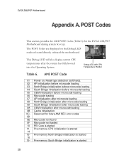
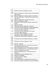
... loading 0A OEM initialization after the system has fully booted into the Operating System. Pre-memory South Bridge initialization is started EVGA Z68/P67 Motherboard This section provides the AMI POST Codes (Table 6) for future AMI SEC error codes 0D 0E Microcode not ...Debug LED readout located directly onboard the motherboard. Debug LED with CPU Temperature Monitor Table 6. This Debug LED will also display current CPU temperatures after microcode loading 0B Cache initialization 0C- Reserved for the EVGA Z68/P67 Motherboard during system boot up. The POST Codes are displayed...
... loading 0A OEM initialization after the system has fully booted into the Operating System. Pre-memory South Bridge initialization is started EVGA Z68/P67 Motherboard This section provides the AMI POST Codes (Table 6) for future AMI SEC error codes 0D 0E Microcode not ...Debug LED readout located directly onboard the motherboard. Debug LED with CPU Temperature Monitor Table 6. This Debug LED will also display current CPU temperatures after microcode loading 0B Cache initialization 0C- Reserved for the EVGA Z68/P67 Motherboard during system boot up. The POST Codes are displayed...
User Guide
Page 29
...-memory initialization. Memory presence detection 2D Memory initialization. Cache initialization 34 CPU post-memory initialization. EVGA Z68/P67 Motherboard 1C 1D- Application Processor(s) (AP) initialization 35 CPU post-memory initialization. Boot Strap Processor (BSP) selection 36 CPU post-memory initialization. SPD reading has failed 52 Memory initialization error. Configuring memory 2F Memory initialization (other). 30...
...-memory initialization. Memory presence detection 2D Memory initialization. Cache initialization 34 CPU post-memory initialization. EVGA Z68/P67 Motherboard 1C 1D- Application Processor(s) (AP) initialization 35 CPU post-memory initialization. Boot Strap Processor (BSP) selection 36 CPU post-memory initialization. SPD reading has failed 52 Memory initialization error. Configuring memory 2F Memory initialization (other). 30...

User Guide
Page 30
... FB- North Bridge DXE initialization (North Bridge 6F module specific) 70 South Bridge DXE initialization is not available 5C- EVGA Z68/P67 Motherboard is failed 5A Internal CPU error 5B reset PPI is started CPU DXE initialization is started 67 68 PCI host bridge initialization 69 North Bridge DXE initialization is started 6A North...
... FB- North Bridge DXE initialization (North Bridge 6F module specific) 70 South Bridge DXE initialization is not available 5C- EVGA Z68/P67 Motherboard is failed 5A Internal CPU error 5B reset PPI is started CPU DXE initialization is started 67 68 PCI host bridge initialization 69 North Bridge DXE initialization is started 6A North...

User Guide
Page 32
EVGA Z68/P67 Motherboard AD Ready To Boot event AE Legacy Boot event AF Exit Boot Services event B0 Runtime Set Virtual Address MAP Begin B1 Runtime ... Clean-up of NVRAM B7 Configuration Reset (reset of Resources D5 No Space for future AMI codes BF C0- OEM BDS initialization codes CF D0 CPU initialization error D1 North Bridge initialization error D2 South Bridge initialization error D3 Some of the Architectural Protocols are found D7 No Console Input Devices...
EVGA Z68/P67 Motherboard AD Ready To Boot event AE Legacy Boot event AF Exit Boot Services event B0 Runtime Set Virtual Address MAP Begin B1 Runtime ... Clean-up of NVRAM B7 Configuration Reset (reset of Resources D5 No Space for future AMI codes BF C0- OEM BDS initialization codes CF D0 CPU initialization error D1 North Bridge initialization error D2 South Bridge initialization error D3 Some of the Architectural Protocols are found D7 No Console Input Devices...

User Guide
Page 33
... and Power Interface BCLK - Digital Versatile Disc DVI - Digital Video Interface FDC - Alternating Current ACPI - Advanced Configuration and Power Interface AFR - Complementary Metal-Oxide Semiconductor CPU - EVGA Z68/P67 Motherboard 1337 - This is reserved for EVGA level elite AC - Advanced Programmable Interrupt Controller ACPI - Base Clock (or operating frequency of base system bus) BIOS -
... and Power Interface BCLK - Digital Versatile Disc DVI - Digital Video Interface FDC - Alternating Current ACPI - Advanced Configuration and Power Interface AFR - Complementary Metal-Oxide Semiconductor CPU - EVGA Z68/P67 Motherboard 1337 - This is reserved for EVGA level elite AC - Advanced Programmable Interrupt Controller ACPI - Base Clock (or operating frequency of base system bus) BIOS -
