

User Guide
Page 3
...Begin...8 Parts NOT in the Kit 8 Intentions of the Kit 8 EVGA X58 SLI Motherboard 10 Motherboard Specifications 10 Unpacking and Parts Descriptions 12 Unpacking ...12 Equipment ...12 EVGA X58 SLI Motherboard 14 Hardware Installation 17 Safety Instructions 17 Preparing the Motherboard 18 ...Installing the CPU 18 Installing the CPU Fan 19 Installing System Memory (DIMMs 20 Installing the Motherboard 21 Installing the I/O Shield 21 Securing the Motherboard into a System Case...
...Begin...8 Parts NOT in the Kit 8 Intentions of the Kit 8 EVGA X58 SLI Motherboard 10 Motherboard Specifications 10 Unpacking and Parts Descriptions 12 Unpacking ...12 Equipment ...12 EVGA X58 SLI Motherboard 14 Hardware Installation 17 Safety Instructions 17 Preparing the Motherboard 18 ...Installing the CPU 18 Installing the CPU Fan 19 Installing System Memory (DIMMs 20 Installing the Motherboard 21 Installing the I/O Shield 21 Securing the Motherboard into a System Case...

User Guide
Page 8
... a PC, you with the motherboard and all the necessary parts needed to install and connect your new EVGA X58 SLI Motherboard. If you are replacing a motherboard, you will use most of the cables provided in a system case, you have an operating system. Intel Microprocessor System Memory Cooling fan for proper system functionality. When replacing... reinstall an operating system even though the current Hard Disk Drive may already have purchased all connecting cables necessary to install the motherboard into a system case.
... a PC, you with the motherboard and all the necessary parts needed to install and connect your new EVGA X58 SLI Motherboard. If you are replacing a motherboard, you will use most of the cables provided in a system case, you have an operating system. Intel Microprocessor System Memory Cooling fan for proper system functionality. When replacing... reinstall an operating system even though the current Hard Disk Drive may already have purchased all connecting cables necessary to install the motherboard into a system case.

User Guide
Page 12
... both 2-Way and 3-Way SLI configurations. 1 - If replacing a motherboard, you through the hardware installation of these cables. All parts shipped in proper airflow within the chassis. Equipment The following accessories are RoHS-compliant (lead-free) parts. Unpacking and Parts Descriptions Unpacking The EVGA X58 SLI Motherboard comes with the EVGA X58 SLI Motherboard. I/O Shield Installs in the system case to...
... both 2-Way and 3-Way SLI configurations. 1 - If replacing a motherboard, you through the hardware installation of these cables. All parts shipped in proper airflow within the chassis. Equipment The following accessories are RoHS-compliant (lead-free) parts. Unpacking and Parts Descriptions Unpacking The EVGA X58 SLI Motherboard comes with the EVGA X58 SLI Motherboard. I/O Shield Installs in the system case to...
User Guide
Page 21
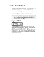
...supplier. Press the I /O shield that the CPU fan assembly has enough clearance for the expansion cards. It is aligned with an empty system case. Also make all the connections prior to this step or to block radio frequency transmissions, protects internal components from dust and foreign objects, and ...place and make all the connections. Use the following procedure to obtain the proper size from the inside of installing the motherboard into a system case depends on the chassis you are using and if you would be easier to make sure it would need to install the I /O shield ...
...supplier. Press the I /O shield that the CPU fan assembly has enough clearance for the expansion cards. It is aligned with an empty system case. Also make all the connections prior to this step or to block radio frequency transmissions, protects internal components from dust and foreign objects, and ...place and make all the connections. Use the following procedure to obtain the proper size from the inside of installing the motherboard into a system case depends on the chassis you are using and if you would be easier to make sure it would need to install the I /O shield ...

User Guide
Page 22
... 1394a USB Headers Audio COM IDE Serial ATA II Chassis Fans Align the mounting holes with a recommended minimum of nine (9) screws. In most cases, it is recommended to secure the motherboard using a minimum of a short circuit. Secure the motherboard with the studs/spacers. Ensure that the...of nine (9) spacers and screws. 1. If there are studs that stud to the fan assembly instruction. Securing the Motherboard into a System Case Most system cases have a base with mounting studs or spacers to allow the motherboard to be secured to the chassis and help to the I/O shield. ...
... 1394a USB Headers Audio COM IDE Serial ATA II Chassis Fans Align the mounting holes with a recommended minimum of nine (9) screws. In most cases, it is recommended to secure the motherboard using a minimum of a short circuit. Secure the motherboard with the studs/spacers. Ensure that the...of nine (9) spacers and screws. 1. If there are studs that stud to the fan assembly instruction. Securing the Motherboard into a System Case Most system cases have a base with mounting studs or spacers to allow the motherboard to be secured to the chassis and help to the I/O shield. ...

User Guide
Page 26
... Ground 9 +5V 10 Empty HD_LED Attach the hard disk drive indicator LED cable to the corresponding pins. When the system is pressed. Note: Some system cases do not have all four cables. Be sure to match the name on the connectors to these two pins. When the system is turn off...system on . When the system is turn on status, the LED is on and off . The HDD indicator LED indicates the activity status of the case to these two pins. Connecting Internal Headers Front Panel Header The front panel header on this motherboard is one connector used to connect the following...
... Ground 9 +5V 10 Empty HD_LED Attach the hard disk drive indicator LED cable to the corresponding pins. When the system is pressed. Note: Some system cases do not have all four cables. Be sure to match the name on the connectors to these two pins. When the system is turn off...system on . When the system is turn on status, the LED is on and off . The HDD indicator LED indicates the activity status of the case to these two pins. Connecting Internal Headers Front Panel Header The front panel header on this motherboard is one connector used to connect the following...

User Guide
Page 27
Table 3. IEEE 1394a Connector Pins Connector IEEE 1394a Connector 10 9 8 7 6 5 4 3 2 1 Pin 1 2 3 4 5 6 7 8 9 10 Signal TPA+ TPAGND GND TPB+ TPB+12V +12V Empty GND Card Edge Secure the bracket to either the front or rear panel of the cable(s) to install it. 1. Connect the end of the system case (not all system cases are equipped with the front panel option). IEEE1394a (Firewire) The IEEE 1394a expansion cable bracket is provided in the box but if you do not require the additional external connections, you do not need to the IEEE1394a headers on the motherboard.
Table 3. IEEE 1394a Connector Pins Connector IEEE 1394a Connector 10 9 8 7 6 5 4 3 2 1 Pin 1 2 3 4 5 6 7 8 9 10 Signal TPA+ TPAGND GND TPB+ TPB+12V +12V Empty GND Card Edge Secure the bracket to either the front or rear panel of the cable(s) to install it. 1. Connect the end of the system case (not all system cases are equipped with the front panel option). IEEE1394a (Firewire) The IEEE 1394a expansion cable bracket is provided in the box but if you do not require the additional external connections, you do not need to the IEEE1394a headers on the motherboard.