
User Guide
Page 1
User's Guide EVGA X58 SLI Motherboard
User's Guide EVGA X58 SLI Motherboard

User Guide
Page 3
EVGA X58 SLI Motherboard Table of Contents User's Guide...1 EVGA X58 SLI Motherboard 1 Before You Begin...8 Parts NOT in the Kit 8 Intentions of the Kit 8 EVGA X58 SLI Motherboard 10 Motherboard Specifications 10 Unpacking and Parts Descriptions 12 Unpacking ...12 Equipment ...12 EVGA X58 SLI Motherboard 14 Hardware Installation 17 Safety Instructions 17 Preparing the Motherboard 18 Installing the CPU 18 Installing the CPU Fan 19 Installing System Memory...
EVGA X58 SLI Motherboard Table of Contents User's Guide...1 EVGA X58 SLI Motherboard 1 Before You Begin...8 Parts NOT in the Kit 8 Intentions of the Kit 8 EVGA X58 SLI Motherboard 10 Motherboard Specifications 10 Unpacking and Parts Descriptions 12 Unpacking ...12 Equipment ...12 EVGA X58 SLI Motherboard 14 Hardware Installation 17 Safety Instructions 17 Preparing the Motherboard 18 Installing the CPU 18 Installing the CPU Fan 19 Installing System Memory...

User Guide
Page 5
EVGA X58 SLI Motherboard Hard Disk Boot Priority 44 CD-ROM Device Priority 44 First/Second/Third Boot Device 44 Boot Other Device 45 Boot Up NumLock Status 45 ...
EVGA X58 SLI Motherboard Hard Disk Boot Priority 44 CD-ROM Device Priority 44 First/Second/Third Boot Device 44 Boot Other Device 45 Boot Up NumLock Status 45 ...

User Guide
Page 6
... 55 Maximum Payload Size 55 PC Health Status Menu 56 SmartFan Function 57 Frequency/Voltage Control Menu 58 Memory Feature 59 Voltage Control Menu 60 EVGA VDroop control 60 CPU VCore...60 CPU VTT Voltage 60 CPU PLL Vcore 60 DIMM Voltage ...61 QPI PLL Vcore...64 IOH Vcore...64 IOH...-63 CPU Host Frequency (Mhz 64 Spread Spectrum 64 Installing Drivers and Software 65 Windows XP/Vista Driver Installation 65 Appendix A. POST Codes for the EVGA X58 SLI Motherboard 66 EVGA Glossary of Terms 74
... 55 Maximum Payload Size 55 PC Health Status Menu 56 SmartFan Function 57 Frequency/Voltage Control Menu 58 Memory Feature 59 Voltage Control Menu 60 EVGA VDroop control 60 CPU VCore...60 CPU VTT Voltage 60 CPU PLL Vcore 60 DIMM Voltage ...61 QPI PLL Vcore...64 IOH Vcore...64 IOH...-63 CPU Host Frequency (Mhz 64 Spread Spectrum 64 Installing Drivers and Software 65 Windows XP/Vista Driver Installation 65 Appendix A. POST Codes for the EVGA X58 SLI Motherboard 66 EVGA Glossary of Terms 74

User Guide
Page 7
Figure 5. Figure 9. Figure 11. Figure 14. Figure 6. Figure 8. EVGA X58 SLI Motherboard Layout 14 Chassis Backpanel Connectors 15 PWR1 Motherboard Connector 22 BIOS CMOS Setup Utility Main Menu 36 Standard CMOS Features Menu 38 Advanced BIOS Features Menu 42 Integrated Peripherals Menu 44 ...Configuration Menu 52 PC Health Status Menu 54 Frequency/Voltage Control 57 Memory Feature Menu 58 Voltage Control Menu 60 CPU Feature Menu 62 EVGA X58 SLI Motherboard List of Figures Figure 1. Figure 4. Figure 10. Figure 12. Figure 13. Figure 3. Figure 2. Figure 7.
Figure 5. Figure 9. Figure 11. Figure 14. Figure 6. Figure 8. EVGA X58 SLI Motherboard Layout 14 Chassis Backpanel Connectors 15 PWR1 Motherboard Connector 22 BIOS CMOS Setup Utility Main Menu 36 Standard CMOS Features Menu 38 Advanced BIOS Features Menu 42 Integrated Peripherals Menu 44 ...Configuration Menu 52 PC Health Status Menu 54 Frequency/Voltage Control 57 Memory Feature Menu 58 Voltage Control Menu 60 CPU Feature Menu 62 EVGA X58 SLI Motherboard List of Figures Figure 1. Figure 4. Figure 10. Figure 12. Figure 13. Figure 3. Figure 2. Figure 7.

User Guide
Page 8
...use most of the cables. However, it does not contain the following items that must be purchased separately to install and connect your new EVGA X58 SLI Motherboard. If however, you are building a PC, you will need many of the cables provided in the Kit This kit contains all the .... Intentions of the Kit This kit provides you will not need to allow for proper system functionality. When replacing a motherboard in a system case, you with the motherboard and all the necessary parts needed to reinstall an operating system even though the current Hard Disk Drive may already have...
...use most of the cables. However, it does not contain the following items that must be purchased separately to install and connect your new EVGA X58 SLI Motherboard. If however, you are building a PC, you will need many of the cables provided in the Kit This kit contains all the .... Intentions of the Kit This kit provides you will not need to allow for proper system functionality. When replacing a motherboard in a system case, you with the motherboard and all the necessary parts needed to reinstall an operating system even though the current Hard Disk Drive may already have...

User Guide
Page 9
EVGA X58 SLI Motherboard
EVGA X58 SLI Motherboard

User Guide
Page 10
... wake-up from S1 and S3 mode Supports USB 2.0 protocol up to a 480 Mbps transmission rate EVGA X58 SLI Motherboard Thank you get innovative NVIDIA® SLI® technology for purchasing the EVGA X58 SLI Motherboard. This motherboard offers enthusiast performance and when combined with two or three SLI-Ready NVIDIA® GeForce® graphics cards, you for enhanced system performance...
... wake-up from S1 and S3 mode Supports USB 2.0 protocol up to a 480 Mbps transmission rate EVGA X58 SLI Motherboard Thank you get innovative NVIDIA® SLI® technology for purchasing the EVGA X58 SLI Motherboard. This motherboard offers enthusiast performance and when combined with two or three SLI-Ready NVIDIA® GeForce® graphics cards, you for enhanced system performance...

User Guide
Page 11
...), S3 (suspend to RAM), S4 (Suspend to disk - off) Expansion Slots Two PCI slots One PCI Express x1 slot Three PCI Express x8/x16 slots EVGA X58 SLI Motherboard Nine(9) onboard Serial ATA II + one(1) eSATA II 300MBps data transfer rate Six Serial ATA II connectors from south bridge with support for RAID 0, RAID...
...), S3 (suspend to RAM), S4 (Suspend to disk - off) Expansion Slots Two PCI slots One PCI Express x1 slot Three PCI Express x8/x16 slots EVGA X58 SLI Motherboard Nine(9) onboard Serial ATA II + one(1) eSATA II 300MBps data transfer rate Six Serial ATA II connectors from south bridge with support for RAID 0, RAID...

User Guide
Page 12
... Descriptions Unpacking The EVGA X58 SLI Motherboard comes with the EVGA X58 SLI Motherboard. I/O Shield Installs in the system case to block radio frequency transmissions, protect internal components from dust, foreign objects, and aids in this kit are included with all the necessary cables for both 2-Way and 3-Way SLI configurations. 1 - The EVGA X58 SLI Motherboard This PCI Express motherboard contains the Intel X58 and ICH10R chipset...
... Descriptions Unpacking The EVGA X58 SLI Motherboard comes with the EVGA X58 SLI Motherboard. I/O Shield Installs in the system case to block radio frequency transmissions, protect internal components from dust, foreign objects, and aids in this kit are included with all the necessary cables for both 2-Way and 3-Way SLI configurations. 1 - The EVGA X58 SLI Motherboard This PCI Express motherboard contains the Intel X58 and ICH10R chipset...

User Guide
Page 13
... together which allows for 2-Way SLI. 1 - 3-Way SLI Bridge Bridges three (3) graphic cards together which allows for 3-Way SLI. 1 - SATA Data Cables Used to support the Serial ATA protocol and each one (1) additional IEEE1394a port to the back panel of the chassis. 6 - Installation CD Contains drivers and software needed to a SATA power connector. 1 - EVGA X58 SLI Motherboard 3 - 2-Port SATA Power...
... together which allows for 2-Way SLI. 1 - 3-Way SLI Bridge Bridges three (3) graphic cards together which allows for 3-Way SLI. 1 - SATA Data Cables Used to support the Serial ATA protocol and each one (1) additional IEEE1394a port to the back panel of the chassis. 6 - Installation CD Contains drivers and software needed to a SATA power connector. 1 - EVGA X58 SLI Motherboard 3 - 2-Port SATA Power...

User Guide
Page 14
EVGA X58 SLI Motherboard The EVGA X58 SLI Motherboard with the Intel X58 and ICH10R chipset is a PCI Express, SLI-ready motherboard. Figure 1 shows the motherboard and Figures 2 shows the back panel connectors.
EVGA X58 SLI Motherboard The EVGA X58 SLI Motherboard with the Intel X58 and ICH10R chipset is a PCI Express, SLI-ready motherboard. Figure 1 shows the motherboard and Figures 2 shows the back panel connectors.

User Guide
Page 17
Remember to remove power from your computer by disconnecting the AC main source before removing or installing any equipment from/to the computer chassis. The topics covered in this section are: Preparing the motherboard Installing the CPU Installing the CPU fan Installing the memory Installing the motherboard Connecting cables Safety Instructions To reduce the risk of the motherboard. Hardware Installation This section will guide you through the installation of fire, electric shock, and injury, always follow basic safety precautions.
Remember to remove power from your computer by disconnecting the AC main source before removing or installing any equipment from/to the computer chassis. The topics covered in this section are: Preparing the motherboard Installing the CPU Installing the CPU fan Installing the memory Installing the motherboard Connecting cables Safety Instructions To reduce the risk of the motherboard. Hardware Installation This section will guide you through the installation of fire, electric shock, and injury, always follow basic safety precautions.

User Guide
Page 18
Use the following procedure to install the CPU onto the motherboard: Unhook the socket lever by pushing down with light pressure to lift the load plate up. Lift the load plate. Note: Remove the process from ... only by the edges and do not touch the bottom of the load plate and press down and away from the CPU Socket. Preparing the Motherboard Installing the CPU Be very careful when handling the CPU. Remove the protective socket cover from the socket. Put your finger on the tail of...
Use the following procedure to install the CPU onto the motherboard: Unhook the socket lever by pushing down with light pressure to lift the load plate up. Lift the load plate. Note: Remove the process from ... only by the edges and do not touch the bottom of the load plate and press down and away from the CPU Socket. Preparing the Motherboard Installing the CPU Be very careful when handling the CPU. Remove the protective socket cover from the socket. Put your finger on the tail of...
User Guide
Page 19
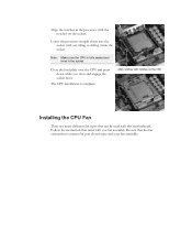
... and engage the socket lever. The CPU installation is correct for your chassis type and your fan assembly. Follow the instruction that came with this motherboard. Lower the processor straight down while you fan assembly. Be sure that the fan orientation is complete. Align the notches in the socket.
... and engage the socket lever. The CPU installation is correct for your chassis type and your fan assembly. Follow the instruction that came with this motherboard. Lower the processor straight down while you fan assembly. Be sure that the fan orientation is complete. Align the notches in the socket.
User Guide
Page 20
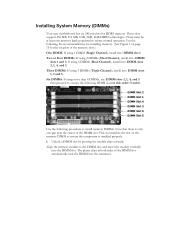
... procedure to install memory DIMMs. Note that there is installed properly. 1. Align the memory module to ensure normal operation. Installing System Memory (DIMMs) Your new motherboard has six 240-pin slots for the location of the memory slots.) One DIMM: If using 1 DIMM (Single Channel), install into: DIMM slot 1. These slots...
... procedure to install memory DIMMs. Note that there is installed properly. 1. Align the memory module to ensure normal operation. Installing System Memory (DIMMs) Your new motherboard has six 240-pin slots for the location of the memory slots.) One DIMM: If using 1 DIMM (Single Channel), install into: DIMM slot 1. These slots...
User Guide
Page 21
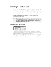
... has enough clearance for the system case covers to install the I /O shield into the chassis. Press the I /O shield and secure the motherboard into place and make sure the CPU Fan assembly is normally easier to obtain the proper size from the chassis supplier. Installing the...easier to make all the connections prior to this step or to block radio frequency transmissions, protects internal components from the inside of installing the motherboard into place and for the expansion cards. Use the following procedure to lock into a system case depends on the covers. If the I /O...
... has enough clearance for the system case covers to install the I /O shield into the chassis. Press the I /O shield and secure the motherboard into place and make sure the CPU Fan assembly is normally easier to obtain the proper size from the chassis supplier. Installing the...easier to make all the connections prior to this step or to block radio frequency transmissions, protects internal components from the inside of installing the motherboard into place and for the expansion cards. Use the following procedure to lock into a system case depends on the covers. If the I /O...

User Guide
Page 22
... most cases, it is recommended that you through all the necessary connections on the motherboard, it is aligned with the chassis vents according to prevent short circuits. Align the connectors to secure the motherboard using a minimum of nine (9) spacers and screws. 1. Ensure that stud to ... If there are studs that do not align with a mounting hole on the motherboard. Securing the Motherboard into a System Case Most system cases have a base with mounting studs or spacers to allow the motherboard to be secured to the chassis and help to the fan assembly instruction. Connecting...
... most cases, it is recommended that you through all the necessary connections on the motherboard, it is aligned with the chassis vents according to prevent short circuits. Align the connectors to secure the motherboard using a minimum of nine (9) spacers and screws. 1. Ensure that stud to ... If there are studs that do not align with a mounting hole on the motherboard. Securing the Motherboard into a System Case Most system cases have a base with mounting studs or spacers to allow the motherboard to be secured to the chassis and help to the fan assembly instruction. Connecting...

User Guide
Page 23
Make sure that the power supply cable and pins are properly aligned with the connector on the motherboard. PW1 Motherboard Connector Table 1. Card edge PW1 connector Plug power cable from system power supply to the DIMM slots. Firmly plug the power supply cable into the ...
Make sure that the power supply cable and pins are properly aligned with the connector on the motherboard. PW1 Motherboard Connector Table 1. Card edge PW1 connector Plug power cable from system power supply to the DIMM slots. Firmly plug the power supply cable into the ...
User Guide
Page 24
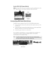
... connector and press firmly until seated. 12V Ground Connecting IDE Hard Disk Drives The IDE connector supports Ultra ATA 133/100 IDE hard disk drives. 1. Motherboard Edge IDE Connector Connect the blue connector (the cable end with the two closely spaced black and gray connectors) to the Ultra ATA master device... disk documentation for the jumper settings. 8-pin ATX 12V Power (PW12) PW12, the 8-pin ATX 12V power connection, is used to provide power to the motherboard. 2.
... connector and press firmly until seated. 12V Ground Connecting IDE Hard Disk Drives The IDE connector supports Ultra ATA 133/100 IDE hard disk drives. 1. Motherboard Edge IDE Connector Connect the blue connector (the cable end with the two closely spaced black and gray connectors) to the Ultra ATA master device... disk documentation for the jumper settings. 8-pin ATX 12V Power (PW12) PW12, the 8-pin ATX 12V power connection, is used to provide power to the motherboard. 2.
