Hardware Reference
Page 4
Chapter 3 Appendix A Brocade 5100 configuration 10 Providing power to the switch 10 Creating a serial connection 11 Switch IP address 11 Date and time settings 12 Brocade 5100 Operation In this chapter 17 Powering the Brocade 5100 on and off 17 LED activity ... 5100 Specifications In this appendix 27 Switch components 27 Weight and physical dimensions 28 Facility requirements 28 Power supply specifications 28 Environmental requirements 29 General specifications 29 Data transmission ranges 30 Memory specifications 31 Fibre Channel port specifications 31 Serial port specifications...
Chapter 3 Appendix A Brocade 5100 configuration 10 Providing power to the switch 10 Creating a serial connection 11 Switch IP address 11 Date and time settings 12 Brocade 5100 Operation In this chapter 17 Powering the Brocade 5100 on and off 17 LED activity ... 5100 Specifications In this appendix 27 Switch components 27 Weight and physical dimensions 28 Facility requirements 28 Power supply specifications 28 Environmental requirements 29 General specifications 29 Data transmission ranges 30 Memory specifications 31 Fibre Channel port specifications 31 Serial port specifications...
Hardware Reference
Page 5
Index Regulatory compliance 32 FCC warning (US only 33 MIC statement (Republic of Korea 33 VCCI statement Japan 33 Power cords (Japan Denan 33 BSMI statement (Taiwan 34 CE statement 34 Canadian requirements 34 Laser compliance 35 RTC battery 35 Electrical safety 35 Regulatory certifications 35 Environmental regulation compliance 36 China RoHS 36 Brocade 5100 Hardware Reference Manual v 53-1000854-02
Index Regulatory compliance 32 FCC warning (US only 33 MIC statement (Republic of Korea 33 VCCI statement Japan 33 Power cords (Japan Denan 33 BSMI statement (Taiwan 34 CE statement 34 Canadian requirements 34 Laser compliance 35 RTC battery 35 Electrical safety 35 Regulatory certifications 35 Environmental regulation compliance 36 China RoHS 36 Brocade 5100 Hardware Reference Manual v 53-1000854-02
Hardware Reference
Page 11
...Brocade DCX. 2. World Wide Name (WWN) Use the wwn command to : [email protected] Provide the title and version number of this document. Switch Serial Number The switch serial number and corresponding bar code are provided on the serial number label, as follows: • Brocade 200E-On the non-port side of... pull-out tab located on the bottom of the port side of the switch • Brocade 7600-On the bottom of the chassis • Brocade 48000-Inside the chassis next to the power supply bays • Brocade DCX-On the bottom right on the WWN cards by removing the Brocade logo ...
...Brocade DCX. 2. World Wide Name (WWN) Use the wwn command to : [email protected] Provide the title and version number of this document. Switch Serial Number The switch serial number and corresponding bar code are provided on the serial number label, as follows: • Brocade 200E-On the non-port side of... pull-out tab located on the bottom of the port side of the switch • Brocade 7600-On the bottom of the chassis • Brocade 48000-Inside the chassis next to the power supply bays • Brocade DCX-On the bottom right on the WWN cards by removing the Brocade logo ...
Hardware Reference
Page 13
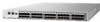
...32 or 40 ports. • Support for 1, 2, 4, and 8 Gbps auto-sensing Fibre Channel switch and router ports. • FICON®, FICON Cascading and FICON Control Unit Port ready. • Two hot-swappable, redundant integrated power supply and fan FRUs. • Universal ports that offers the next generation Brocade, single-chip... on Demand license 5 •ISL trunking groups 5 Brocade 5100 overview The Brocade 5100 is an Enterprise class 1U, 40-port Fibre Channel 1, 2, 4 or 8 Gbps Fibre Channel switch that self-configure as the foundation of entry-to medium-sized work groups.
...32 or 40 ports. • Support for 1, 2, 4, and 8 Gbps auto-sensing Fibre Channel switch and router ports. • FICON®, FICON Cascading and FICON Control Unit Port ready. • Two hot-swappable, redundant integrated power supply and fan FRUs. • Universal ports that offers the next generation Brocade, single-chip... on Demand license 5 •ISL trunking groups 5 Brocade 5100 overview The Brocade 5100 is an Enterprise class 1U, 40-port Fibre Channel 1, 2, 4 or 8 Gbps Fibre Channel switch that self-configure as the foundation of entry-to medium-sized work groups.
Hardware Reference
Page 15
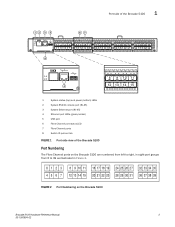
...11 4 12 13 14 15 1 System status (top) and power (bottom) LEDs 2 System RS232 console port (RJ-45) 3 System Ethernet port (RJ-45) 4 Ethernet port LEDs (green/amber) 5 USB port 6 Fibre Channel port status LED 7 Fibre Channel ports 8 Switch ID pull-out tab FIGURE 1 Port-side view of the ...Brocade 5100 Port Numbering The Fibre Channel ports on the Brocade 5100 are numbered from left to right, in eight-port...
...11 4 12 13 14 15 1 System status (top) and power (bottom) LEDs 2 System RS232 console port (RJ-45) 3 System Ethernet port (RJ-45) 4 Ethernet port LEDs (green/amber) 5 USB port 6 Fibre Channel port status LED 7 Fibre Channel ports 8 Switch ID pull-out tab FIGURE 1 Port-side view of the ...Brocade 5100 Port Numbering The Fibre Channel ports on the Brocade 5100 are numbered from left to right, in eight-port...

Hardware Reference
Page 16
...-fan assemblies and the corresponding status LEDs. Non-port side of the Brocade 5100 The non-port side of the entire switch, including the two power supply/fan assembly FRUs. 4 Brocade 5100 Hardware Reference Manual 53-1000854-02 The front panel has a status LED that allows you to the Brocade Fabric ...
...-fan assemblies and the corresponding status LEDs. Non-port side of the Brocade 5100 The non-port side of the entire switch, including the two power supply/fan assembly FRUs. 4 Brocade 5100 Hardware Reference Manual 53-1000854-02 The front panel has a status LED that allows you to the Brocade Fabric ...

Hardware Reference
Page 19
...5100 configuration 10 Items included with the Brocade 5100 The following items are included in the following ways: 1. Power Cord • Rubber feet, required for setting up the switch as a standalone unit • Brocade Family Doc CD • Brocade 5100 QuickStart Guide • EZSwitchSetup ...slide-rail rack, you open the Brocade 5100 packaging, verify that no damage has occurred during shipping: • The Brocade 5100 switch, containing two power supply/fan assembly units • One accessory kit containing: • Serial Cable with the standard shipment of the Brocade 5100. In...
...5100 configuration 10 Items included with the Brocade 5100 The following items are included in the following ways: 1. Power Cord • Rubber feet, required for setting up the switch as a standalone unit • Brocade Family Doc CD • Brocade 5100 QuickStart Guide • EZSwitchSetup ...slide-rail rack, you open the Brocade 5100 packaging, verify that no damage has occurred during shipping: • The Brocade 5100 switch, containing two power supply/fan assembly units • One accessory kit containing: • Serial Cable with the standard shipment of the Brocade 5100. In...
Hardware Reference
Page 20
... following: • The primary outlet is correctly wired, protected by the electrical rating on the switch nameplate. • The power supply standards provided in Table 5, "Power Supply Specifications" on the non-port side of unexpected movement, such as a power strip. • Ensure that airflow and temperature requirements are met on an ongoing basis, particularly...
... following: • The primary outlet is correctly wired, protected by the electrical rating on the switch nameplate. • The power supply standards provided in Table 5, "Power Supply Specifications" on the non-port side of unexpected movement, such as a power strip. • Ensure that airflow and temperature requirements are met on an ongoing basis, particularly...
Hardware Reference
Page 21
...the adhesion of the feet. Apply the adhesive rubber feet. b. Place the switch on page 7. Verify the items are using cable channels on page 10. Applying the rubber feet onto the switch helps prevent the switch from being bent to less than the minimum bend radius. • If... you are present and undamaged. 2. a. Provide power to the switch as a standalone unit. 1. With the ...
...the adhesion of the feet. Apply the adhesive rubber feet. b. Place the switch on page 7. Verify the items are using cable channels on page 10. Applying the rubber feet onto the switch helps prevent the switch from being bent to less than the minimum bend radius. • If... you are present and undamaged. 2. a. Provide power to the switch as a standalone unit. 1. With the ...
Hardware Reference
Page 22
... and turned on how to set . You can be installed in the fiber optic cables. Connect the power cords to both AC switches to the "1" symbol. The power supply LEDs display amber until the IP address is correctly set the IP address, see "Brocade 5100 configuration...-Mount Rack Mount Kit (Switch) Installation Procedure. Power on the power supplies by flipping both power supplies, and then to power sources on separate circuits to protect against AC failure. ATTENTION Power is supplied to the switch as soon as a standalone switch, it is time to give it power and a basic configuration....
... and turned on how to set . You can be installed in the fiber optic cables. Connect the power cords to both AC switches to the "1" symbol. The power supply LEDs display amber until the IP address is correctly set the IP address, see "Brocade 5100 configuration...-Mount Rack Mount Kit (Switch) Installation Procedure. Power on the power supplies by flipping both power supplies, and then to power sources on separate circuits to protect against AC failure. ATTENTION Power is supplied to the switch as soon as a standalone switch, it is time to give it power and a basic configuration....
Hardware Reference
Page 23
... a serial connection You will perform all basic configuration tasks in use, use ttya instead and enter the following steps to a DHCP server that the switch power and status LEDs on the left of the port side of the serial cable and insert the exposed RJ-45 connector into the RJ-45... Setting a static IP address Perform the following string at the prompt: tip /dev/ttyb -9600 If ttyb is not on the same subnet as the switch. If the serial port on the workstation is enabled by default. The Brocade 5100 supports both IPv4 and IPv6. Brocade 5100 configuration 2 3. Open a terminal...
... a serial connection You will perform all basic configuration tasks in use, use ttya instead and enter the following steps to a DHCP server that the switch power and status LEDs on the left of the port side of the serial cable and insert the exposed RJ-45 connector into the RJ-45... Setting a static IP address Perform the following string at the prompt: tip /dev/ttyb -9600 If ttyb is not on the same subnet as the switch. If the serial port on the workstation is enabled by default. The Brocade 5100 supports both IPv4 and IPv6. Brocade 5100 configuration 2 3. Open a terminal...
Hardware Reference
Page 29
... of the LEDs on the switch. The switch runs POST by setting each AC power switch to a power source; Sometimes, the LEDs flash either of the switch Brocade 5100 Hardware Reference Manual 17 53-1000854-02 To power the Brocade 5100 off, power off To power the Brocade 5100 on, connect one for each Fibre Channel port, located above ) on the...
... of the LEDs on the switch. The switch runs POST by setting each AC power switch to a power source; Sometimes, the LEDs flash either of the switch Brocade 5100 Hardware Reference Manual 17 53-1000854-02 To power the Brocade 5100 off, power off To power the Brocade 5100 on, connect one for each Fibre Channel port, located above ) on the...

Hardware Reference
Page 30
... 33 34 35 36 37 38 39 3 8 9 10 11 2 12 13 14 15 FIGURE 4 Brocade 5100 port side LEDs 1 System status LED (top) and System power (bottom) 2 Ethernet port Status LEDs (green/amber) 3 FC port status (port 9) Figure 5 shows the non-port side LEDs on the Brocade 5100. 1 2 FIGURE 5 Brocade 5100...
... 33 34 35 36 37 38 39 3 8 9 10 11 2 12 13 14 15 FIGURE 4 Brocade 5100 port side LEDs 1 System status LED (top) and System power (bottom) 2 Ethernet port Status LEDs (green/amber) 3 FC port status (port 9) Figure 5 shows the non-port side LEDs on the Brocade 5100. 1 2 FIGURE 5 Brocade 5100...
Hardware Reference
Page 31
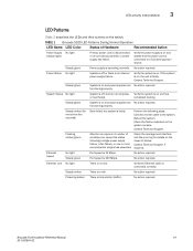
... Hardware Reference Manual 19 53-1000854-02 If the system is on the switch. System Status No light System is off or there is connected correctly. Contact Technical Support. A number of variables can cause this status including a single power supply failure, a fan failure, or one or more than five seconds) Boot failed...
... Hardware Reference Manual 19 53-1000854-02 If the system is on the switch. System Status No light System is off or there is connected correctly. Contact Technical Support. A number of variables can cause this status including a single power supply failure, a fan failure, or one or more than five seconds) Boot failed...
Hardware Reference
Page 33
... 5100 does not require any regular physical maintenance and is complete: 1. Boot In addition to detect if beaconing is no switch prompt when POST completes, press Enter. Performs universal port configuration. 2. Analyzes fabric. Any errors detected during POST are not...operation. If any errors were detected: 1. For information about all components are connected to Fabric OS Administrator's Guide. If this is powered on several functions, including circuitry, port functionality, memory, statistics counters, and serialization. Runs diagnostic tests on , rebooted, or reset....
... 5100 does not require any regular physical maintenance and is complete: 1. Boot In addition to detect if beaconing is no switch prompt when POST completes, press Enter. Performs universal port configuration. 2. Analyzes fabric. Any errors detected during POST are not...operation. If any errors were detected: 1. For information about all components are connected to Fabric OS Administrator's Guide. If this is powered on several functions, including circuitry, port functionality, memory, statistics counters, and serialization. Runs diagnostic tests on , rebooted, or reset....
Hardware Reference
Page 35
...connection to be connected by command, either slot. They are keyed to display power supply status as follows (viewing the switch from the port side): • Power supply #1 is on the left • Power supply #2 is OK Brocade 5100 Hardware Reference Manual 23 53-1000854-02 ...prompt to ensure correct orientation during diagnostic testing. Diagnostic tests are implemented by external cables, to allow diagnostics to the I/O switch. The power supply/fan assembly units are identical and fit into either through a Telnet session or through the tachometer interface. Use one fan...
...connection to be connected by command, either slot. They are keyed to display power supply status as follows (viewing the switch from the port side): • Power supply #1 is on the left • Power supply #2 is OK Brocade 5100 Hardware Reference Manual 23 53-1000854-02 ...prompt to ensure correct orientation during diagnostic testing. Diagnostic tests are implemented by external cables, to allow diagnostics to the I/O switch. The power supply/fan assembly units are identical and fit into either through a Telnet session or through the tachometer interface. Use one fan...
Hardware Reference
Page 36
... OK, speed is 7258 RPM For further information on replacing the power/fan units, see Figure 4 on page 18 for the Brocade 5100 Switch Management Tool Out-of failure. Any errors are recorded in -band interface (over HBA only) IP over Fibre Channel 24 Brocade 5100 Hardware Reference Manual 53-1000854-02 For information...
... OK, speed is 7258 RPM For further information on replacing the power/fan units, see Figure 4 on page 18 for the Brocade 5100 Switch Management Tool Out-of failure. Any errors are recorded in -band interface (over HBA only) IP over Fibre Channel 24 Brocade 5100 Hardware Reference Manual 53-1000854-02 For information...
Hardware Reference
Page 39
Brocade 5100 Specifications Appendix A In this appendix •Switch components 27 •Weight and physical dimensions 28 •Facility requirements 28 •Power supply specifications 28 •Environmental requirements 29 •General specifications 29 •Data transmission ranges 30 •Memory specifications 31 •Fibre Channel port specifications 31 •Serial port specifications 32 •...
Brocade 5100 Specifications Appendix A In this appendix •Switch components 27 •Weight and physical dimensions 28 •Facility requirements 28 •Power supply specifications 28 •Environmental requirements 29 •General specifications 29 •Data transmission ranges 30 •Memory specifications 31 •Fibre Channel port specifications 31 •Serial port specifications 32 •...

Hardware Reference
Page 40
...Inlet Maximum output of the Brocade 5100. Each power supply has a built-in fan for complete power supply specifications. • A minimum air flow of 79.8 cubic meters/hour (47 cubic ft/min.) available in the immediate vicinity of the switch • Ambient air temperature not exceeding 40°...; C (104° F) while the switch is operating • One rack ...
...Inlet Maximum output of the Brocade 5100. Each power supply has a built-in fan for complete power supply specifications. • A minimum air flow of 79.8 cubic meters/hour (47 cubic ft/min.) available in the immediate vicinity of the switch • Ambient air temperature not exceeding 40°...; C (104° F) while the switch is operating • One rack ...
Hardware Reference
Page 41
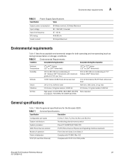
.... TABLE 7 General Specifications Specification Description Configurable port types System architecture System processor ANSI Fibre Channel protocol E_Port, F_Port, FL_Port, M_Port, and EX_Port Nonblocking shared-memory switch Power PC 440EPX,667 MHz CPU FC-PH (Fibre Channel Physical and Signalling Interface standard) Modes of operation Fibre Channel Class 2 and Class 3 Fabric initialization Complies with FC-SW-3 Rev. 6.6 FC-IP...
.... TABLE 7 General Specifications Specification Description Configurable port types System architecture System processor ANSI Fibre Channel protocol E_Port, F_Port, FL_Port, M_Port, and EX_Port Nonblocking shared-memory switch Power PC 440EPX,667 MHz CPU FC-PH (Fibre Channel Physical and Signalling Interface standard) Modes of operation Fibre Channel Class 2 and Class 3 Fabric initialization Complies with FC-SW-3 Rev. 6.6 FC-IP...