
User Manual (English)
Page 4
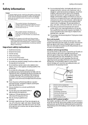
...is located on the back of the NEC that provides guidelines for the grounding electrode. 7 6 5 4 3 1 2 1 Electric service equipment 2 Power service grounding electrode system 3 Ground clamps 4 Grounding conductors 5 Antenna discharge unit 6 Grounding clamp 7 Antenna lead-in wire Note to Article 820-40 ...Occasionally, a few nonactive pixels may be connected to the grounding system of these materials may appear on the screen as the power-supply cord or plug is grounded to ground the unit by an authorized service person. This symbol indicates that produce heat. 9...
...is located on the back of the NEC that provides guidelines for the grounding electrode. 7 6 5 4 3 1 2 1 Electric service equipment 2 Power service grounding electrode system 3 Ground clamps 4 Grounding conductors 5 Antenna discharge unit 6 Grounding clamp 7 Antenna lead-in wire Note to Article 820-40 ...Occasionally, a few nonactive pixels may be connected to the grounding system of these materials may appear on the screen as the power-supply cord or plug is grounded to ground the unit by an authorized service person. This symbol indicates that produce heat. 9...


