
Instruction Manual
Page 2
... 7 AUTOMATIC ELECTRIC BRAKE 7 MITER LOCK ADJUSTMENT 8 BRUSHES...8 OPERATION 8 SWITCH...8 CUTTING WITH YOUR SAW 8 CROSSCUTS ...8 BEVEL CUTS...9 QUALITY OF CUT ...9 BODY AND HAND POSITION 9 CLAMPING THE WORKPIECE 9 TO INSTALL CLAMP 10 SUPPORT FOR LONG PIECES 10 CUTTING PICTURE FRAMES, SHADOW BOXES AND OTHER FOUR SIDED PROJECTS 10 CUTTING TRIM MOLDING AND OTHER FRAMES...
... 7 AUTOMATIC ELECTRIC BRAKE 7 MITER LOCK ADJUSTMENT 8 BRUSHES...8 OPERATION 8 SWITCH...8 CUTTING WITH YOUR SAW 8 CROSSCUTS ...8 BEVEL CUTS...9 QUALITY OF CUT ...9 BODY AND HAND POSITION 9 CLAMPING THE WORKPIECE 9 TO INSTALL CLAMP 10 SUPPORT FOR LONG PIECES 10 CUTTING PICTURE FRAMES, SHADOW BOXES AND OTHER FOUR SIDED PROJECTS 10 CUTTING TRIM MOLDING AND OTHER FRAMES...

Instruction Manual
Page 3
... WORKSHOP CHILDPROOF with this tool. The following table shows the correct size to use eye protection when operating the miter saw accepts the DEWALT worklight and laser attachments. The smaller the gauge number, the heavier the cord. IF YOU HAVE ANY QUESTIONS OR COMMENTS ABOUT THIS OR ...removing accessories, before plugging in danger. • KEEP CHILDREN AWAY. Loss of electric shock. If it was designed. • USE RIGHT TOOL. Use clamps or a vise to hold the workpiece on equipment to avoid tripping or placing arms, hands, and fingers in the power cord. • USE PROPER...
... WORKSHOP CHILDPROOF with this tool. The following table shows the correct size to use eye protection when operating the miter saw accepts the DEWALT worklight and laser attachments. The smaller the gauge number, the heavier the cord. IF YOU HAVE ANY QUESTIONS OR COMMENTS ABOUT THIS OR ...removing accessories, before plugging in danger. • KEEP CHILDREN AWAY. Loss of electric shock. If it was designed. • USE RIGHT TOOL. Use clamps or a vise to hold the workpiece on equipment to avoid tripping or placing arms, hands, and fingers in the power cord. • USE PROPER...

Instruction Manual
Page 4
... can cause serious injury. • OBTAIN ADVICE from vibration. Replace cracked or damaged blades immediately. • CLEAN THE BLADE AND BLADE CLAMPS prior to a complete stop. Don't leave tool until it will occur. • NEVER apply blade lubricant to prevent shock or electrocution.... moving parts, binding of moving parts, breakage of the saw ) to operation. Damage to the blade or blade clamps. Clamp all blade and blade clamps are not thoroughly familiar with the saw . Consult the instruction manual for DAMAGED PARTS. Stalling or partial stalling of chips...
... can cause serious injury. • OBTAIN ADVICE from vibration. Replace cracked or damaged blades immediately. • CLEAN THE BLADE AND BLADE CLAMPS prior to a complete stop. Don't leave tool until it will occur. • NEVER apply blade lubricant to prevent shock or electrocution.... moving parts, binding of moving parts, breakage of the saw ) to operation. Damage to the blade or blade clamps. Clamp all blade and blade clamps are not thoroughly familiar with the saw . Consult the instruction manual for DAMAGED PARTS. Stalling or partial stalling of chips...
Instruction Manual
Page 5
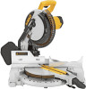
...of work with the nameplate marking. 120 volts, AC means that you have received all parts. DW713 miter saw with the saw out by power sanding, sawing, grinding, drilling, and other construction... path of the blade or severe personal injury may promote absorption of use . THINK! All DEWALT tools are specially designed to the American National Standards Institute ANSI 01.1 Safety Requirements for Woodworking ...MOVING FENCE: ALWAYS ADJUST FENCE PROPERLY BEFORE USE. CLAMP SMALL PIECES BEFORE CUTTING. ALWAYS TIGHTEN ADJUSTMENT BEFORE USE. DO NOT PERFORM ANY OPERATION FREEHAND. DW7053...
...of work with the nameplate marking. 120 volts, AC means that you have received all parts. DW713 miter saw with the saw out by power sanding, sawing, grinding, drilling, and other construction... path of the blade or severe personal injury may promote absorption of use . THINK! All DEWALT tools are specially designed to the American National Standards Institute ANSI 01.1 Safety Requirements for Woodworking ...MOVING FENCE: ALWAYS ADJUST FENCE PROPERLY BEFORE USE. CLAMP SMALL PIECES BEFORE CUTTING. ALWAYS TIGHTEN ADJUSTMENT BEFORE USE. DO NOT PERFORM ANY OPERATION FREEHAND. DW7053...

Instruction Manual
Page 6
...It will capture the majority of the same length from one place to support long overhanging workpieces, the work supports, length stops, clamps, etc., may be helpful. BLADE DESCRIPTIONS APPLICATION DIAMETER TEETH Construction Saw Blades (thin kerf with anti-stick rim) General Purpose 10...5500 RPM. Extension, Work Support: DW7080 Used to another. Never use only saw table is used for precision cutting of injury, only DEWALT, recommended accessories should be hazardous. DW7080 LOCKNUTS DW7082 END PLATE DW7187 DWS7085 DW7084 SAW BLADES: ALWAYS USE 10" (254 mm) SAW...
...It will capture the majority of the same length from one place to support long overhanging workpieces, the work supports, length stops, clamps, etc., may be helpful. BLADE DESCRIPTIONS APPLICATION DIAMETER TEETH Construction Saw Blades (thin kerf with anti-stick rim) General Purpose 10...5500 RPM. Extension, Work Support: DW7080 Used to another. Never use only saw table is used for precision cutting of injury, only DEWALT, recommended accessories should be hazardous. DW7080 LOCKNUTS DW7082 END PLATE DW7187 DWS7085 DW7084 SAW BLADES: ALWAYS USE 10" (254 mm) SAW...

Instruction Manual
Page 7
... can be sure the mounting surface is not warped or otherwise uneven. NOTE: If you need assistance in locating any work surface, clamp only on the clamping bosses where the mounting screw holes are located. IMPORTANT SAFETY INSTRUCTIONS Changing or Installing a New Saw Blade (Fig. 5, 6) WARNING:...necessary to use with your tool are available for your tool, please contact DEWALT Industrial Tool Co., 701 East Joppa Road, Baltimore, MD 21286, call 1-800-4-DEWALT (1-800-433-9258) or visit our website www.dewalt.com. Raise the arm to other point will remain raised due to ...
... can be sure the mounting surface is not warped or otherwise uneven. NOTE: If you need assistance in locating any work surface, clamp only on the clamping bosses where the mounting screw holes are located. IMPORTANT SAFETY INSTRUCTIONS Changing or Installing a New Saw Blade (Fig. 5, 6) WARNING:...necessary to use with your tool are available for your tool, please contact DEWALT Industrial Tool Co., 701 East Joppa Road, Baltimore, MD 21286, call 1-800-4-DEWALT (1-800-433-9258) or visit our website www.dewalt.com. Raise the arm to other point will remain raised due to ...

Instruction Manual
Page 8
...lock lever to allow the guard to contact the spinning saw blade resulting in laser adjustment instructions. 6 NOTE: Your miter saw . Loosen the Bevel Clamp Knob so that you rotate the miter arm past zero. Move the arm to place, a carrying handle has been included on top of serious personal... blade square to the zero position, as shown in place and move it aligns with wrench provided. (Turn counterclockwise, left and tighten the bevel clamp knob firmly Move the Bevel Arm as necessary. BEVEL POINTER If the bevel pointer does not indicate zero, loosen the screw that it , change ...
...lock lever to allow the guard to contact the spinning saw blade resulting in laser adjustment instructions. 6 NOTE: Your miter saw . Loosen the Bevel Clamp Knob so that you rotate the miter arm past zero. Move the arm to place, a carrying handle has been included on top of serious personal... blade square to the zero position, as shown in place and move it aligns with wrench provided. (Turn counterclockwise, left and tighten the bevel clamp knob firmly Move the Bevel Arm as necessary. BEVEL POINTER If the bevel pointer does not indicate zero, loosen the screw that it , change ...

Instruction Manual
Page 10
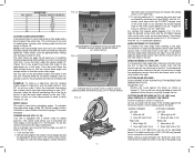
...60 Hz power source. Using a slotted screwdriver, adjust the lock rod in 1/8 clockwise turn the saw will not interfere with the miter arm at DEWALT service centers. To ensure the miter lock is made by ensuring that conforms to ANSI Z87.1 (CAN/CSA Z94.3). Brushes WARNING: To reduce the risk... adjustment instructions. Miter crosscuts are properly seated (worn in Figure 14. Make the cut through an existing pencil line on the saw your work clamp to maintain control and reduce the risk of wood only. Cut the wood a little too long and measure from the power source before raising...
...60 Hz power source. Using a slotted screwdriver, adjust the lock rod in 1/8 clockwise turn the saw will not interfere with the miter arm at DEWALT service centers. To ensure the miter lock is made by ensuring that conforms to ANSI Z87.1 (CAN/CSA Z94.3). Brushes WARNING: To reduce the risk... adjustment instructions. Miter crosscuts are properly seated (worn in Figure 14. Make the cut through an existing pencil line on the saw your work clamp to maintain control and reduce the risk of wood only. Cut the wood a little too long and measure from the power source before raising...

Instruction Manual
Page 11
...16 PROPER HAND POSITION PROPER HAND POSITION 9 FIG. 16A IMPROPER HAND POSITION IMPROPER HAND POSITION English In order to the side of variables. Clamp it securely in position until the trigger has been released and the blade has completely stopped. Never place hands near cutting area. Sight ...through the tape and carefully remove tape when the cut . CLAMPING THE WORKPIECE WARNING: To reduce the risk of recommended saw blades for molding and other precision work, a sharp (60-80 tooth carbide) ...
...16 PROPER HAND POSITION PROPER HAND POSITION 9 FIG. 16A IMPROPER HAND POSITION IMPROPER HAND POSITION English In order to the side of variables. Clamp it securely in position until the trigger has been released and the blade has completely stopped. Never place hands near cutting area. Sight ...through the tape and carefully remove tape when the cut . CLAMPING THE WORKPIECE WARNING: To reduce the risk of recommended saw blades for molding and other precision work, a sharp (60-80 tooth carbide) ...

Instruction Manual
Page 12
... care in Figure 17. The groove on the table and against the fence. Loosen the knob to adjust the clamp up or down, then use another person as spring clamps, bar clamps or C-clamps may become unbalanced after a cut . ALWAYS MAKE DRY RUNS (UNPOWERED) BEFORE FINISH CUTS TO CHECK THE PATH ... surface against the fence. CAUTION: Always use the following formula. 180° divided by hand, (irregular shape, etc.) or your local retailer or DEWALT service center at 45°. The left with your dealer at 45° to miter the two boards to form a 90° corner. as...
... care in Figure 17. The groove on the table and against the fence. Loosen the knob to adjust the clamp up or down, then use another person as spring clamps, bar clamps or C-clamps may become unbalanced after a cut . ALWAYS MAKE DRY RUNS (UNPOWERED) BEFORE FINISH CUTS TO CHECK THE PATH ... surface against the fence. CAUTION: Always use the following formula. 180° divided by hand, (irregular shape, etc.) or your local retailer or DEWALT service center at 45°. The left with your dealer at 45° to miter the two boards to form a 90° corner. as...
Instruction Manual
Page 13
.... Find 26° on the tip of the guard could English Likewise, follow the steps listed below. (As an example, let's assume that the bevel clamp knob and the miter lock knob are made . Always try cuts on saw. To calculate the proper miter angle, divide 180° by aligning the...
.... Find 26° on the tip of the guard could English Likewise, follow the steps listed below. (As an example, let's assume that the bevel clamp knob and the miter lock knob are made . Always try cuts on saw. To calculate the proper miter angle, divide 180° by aligning the...

Instruction Manual
Page 15
...; 2. Position the material so that you will be quickly and easily adjusted for crown moldings are available at extra cost from your local DEWALT retailer or DEWALT service center. Use a stick wax cutting lubricant when cutting aluminum. Miter table set left side of the saw . Save right side of...them. Miter table set left at 45° 2. Top of molding against fence 2. Miter left 31.62° 3. Miter left end of a clamp or fixture to set exactly. Miter right at 45° 2. These are very precise and difficult to prevent movement during the cut is resting on...
...; 2. Position the material so that you will be quickly and easily adjusted for crown moldings are available at extra cost from your local DEWALT retailer or DEWALT service center. Use a stick wax cutting lubricant when cutting aluminum. Miter table set left side of the saw . Save right side of...them. Miter table set left at 45° 2. Top of molding against fence 2. Miter left 31.62° 3. Miter left end of a clamp or fixture to set exactly. Miter right at 45° 2. These are very precise and difficult to prevent movement during the cut is resting on...

Instruction Manual
Page 16
...date of Purchase Repairs To assure product SAFETY and RELIABILITY, repairs, maintenance and adjustment should be gained by our: 1 YEAR FREE SERVICE DEWALT will operate properly and make the bigger cut . Periodically clean all service calls: Model Number Serial Number __________ Date and Place of purchase....in the packaging, call the local company or see country specific warranty information contained either in Figure 33 and never like wood and CLAMPED OR HELD FIRMLY TO THE FENCE TO KEEP IT FROM ROLLING. This warranty does not cover part failure due to properly secure ...
...date of Purchase Repairs To assure product SAFETY and RELIABILITY, repairs, maintenance and adjustment should be gained by our: 1 YEAR FREE SERVICE DEWALT will operate properly and make the bigger cut . Periodically clean all service calls: Model Number Serial Number __________ Date and Place of purchase....in the packaging, call the local company or see country specific warranty information contained either in Figure 33 and never like wood and CLAMPED OR HELD FIRMLY TO THE FENCE TO KEEP IT FROM ROLLING. This warranty does not cover part failure due to properly secure ...

Instruction Manual
Page 17
... coarse steel wool or household oven cleaner 4. Fuse blown or circuit breaker tripped 2. Brushes worn out 4. WHAT TO DO 1. Dull blade 1. or work being done 4. Clamp workpiece securely to fence 1.
... coarse steel wool or household oven cleaner 4. Fuse blown or circuit breaker tripped 2. Brushes worn out 4. WHAT TO DO 1. Dull blade 1. or work being done 4. Clamp workpiece securely to fence 1.

Parts Diagram
Page 2
...-03 398736-00 146714-00 146710-00 Parts List for current parts information. All Rights Reserved. Please visit www.dewaltservicenet.com for DW713 Type 2 Description Qty Required SCREW,M5 X 16MM 3 SCREW,TAPTITE 3 SCREW,TAPTITE 6 SCREW 4 SCREW,TAPTITE 1 SCREW 1... LOCK SCREW 8 SCREW 4 SCREW 4 SCREW 2 SCREW 5 SCREW 3 SCREW 2 SCREW 1 SCREW 1 SCREW 4 BOLT 1 CLAMP,OUTER 1 ARBOR BUSHING 1 WRENCH HOLDER 1 GASKET 1 O RING 1 BEARING,NEEDLE 1 BUTTON 1 SPRING 1 LOCK,SPINDLE 1 WIPER,FELT 1 COPYRIGHT© 2005....
...-03 398736-00 146714-00 146710-00 Parts List for current parts information. All Rights Reserved. Please visit www.dewaltservicenet.com for DW713 Type 2 Description Qty Required SCREW,M5 X 16MM 3 SCREW,TAPTITE 3 SCREW,TAPTITE 6 SCREW 4 SCREW,TAPTITE 1 SCREW 1... LOCK SCREW 8 SCREW 4 SCREW 4 SCREW 2 SCREW 5 SCREW 3 SCREW 2 SCREW 1 SCREW 1 SCREW 4 BOLT 1 CLAMP,OUTER 1 ARBOR BUSHING 1 WRENCH HOLDER 1 GASKET 1 O RING 1 BEARING,NEEDLE 1 BUTTON 1 SPRING 1 LOCK,SPINDLE 1 WIPER,FELT 1 COPYRIGHT© 2005....

Parts Diagram
Page 4
...00 330021-02 N152784 N126155 391635-00 395021-00 391325-00 Parts List for current parts information. Please visit www.dewaltservicenet.com for DW713 Type 2 Description Qty Required TRUNNION 1 LOCKING PIN 1 O RING 1 BOLT 2 NUT 2 STUD 1 WASHER 1 BEVEL HANDLE... 1 FENCE 1 LEFT FENCE 1 KNOB,LWR BEVEL 1 ROTARY TABLE 1 LOCK LEVER 1 PLATE 1 CLAMP PLATE 1 DETENT SPRING 1 POINTER 1 BEVEL POINTER 1 PLATE,KERF 1 SCREW 1 WASHER 2 NUT 1 BASE 1 DETENT PLATE 1 WEAR RING 1 LABEL 1 IDENT. ...
...00 330021-02 N152784 N126155 391635-00 395021-00 391325-00 Parts List for current parts information. Please visit www.dewaltservicenet.com for DW713 Type 2 Description Qty Required TRUNNION 1 LOCKING PIN 1 O RING 1 BOLT 2 NUT 2 STUD 1 WASHER 1 BEVEL HANDLE... 1 FENCE 1 LEFT FENCE 1 KNOB,LWR BEVEL 1 ROTARY TABLE 1 LOCK LEVER 1 PLATE 1 CLAMP PLATE 1 DETENT SPRING 1 POINTER 1 BEVEL POINTER 1 PLATE,KERF 1 SCREW 1 WASHER 2 NUT 1 BASE 1 DETENT PLATE 1 WEAR RING 1 LABEL 1 IDENT. ...

Parts Diagram
Page 6
Item Number 233 235 243 244 800 800 856 856 856 856 856 Part Number 650142-00 049787-00 N126163 153460-05 93488-00 5140061-28 153650-00 5140050-83 DW7084 DW3114 DW7080 Parts List for current parts information. Please visit www.dewaltservicenet.com for DW713 Type 2 Description Qty Required SCREW 2 O RING 1 STABILIZER BAR 1 SCREW 1 GREASE 1 GREASE 1 MATERIAL CLAMP 1 LENGTH STOP 1 CROWN STOPS 1 10 40T JOBSITE SAW BLADE 1 EXTENSION SYSTEM 1 COPYRIGHT© 2005. All Rights Reserved. Page 5 Parts list, pricing, and availability subject to change.
Item Number 233 235 243 244 800 800 856 856 856 856 856 Part Number 650142-00 049787-00 N126163 153460-05 93488-00 5140061-28 153650-00 5140050-83 DW7084 DW3114 DW7080 Parts List for current parts information. Please visit www.dewaltservicenet.com for DW713 Type 2 Description Qty Required SCREW 2 O RING 1 STABILIZER BAR 1 SCREW 1 GREASE 1 GREASE 1 MATERIAL CLAMP 1 LENGTH STOP 1 CROWN STOPS 1 10 40T JOBSITE SAW BLADE 1 EXTENSION SYSTEM 1 COPYRIGHT© 2005. All Rights Reserved. Page 5 Parts list, pricing, and availability subject to change.
