
Instruction Manual
Page 2
.../POLARIZED PLUG INSTRUCTIONS 1 SAFETY INSTRUCTIONS FOR ALL TOOLS 1 ADDITIONAL SAFETY RULES 2 ELECTRICAL CONNECTION 3 UNPACKING YOUR SAW 3 FAMILIARIZATION 3 SPECIFICATIONS 4 OPTIONAL ACCESSORIES 4 ACCESSORIES ...4 BENCH MOUNTING 5 CHANGING OR INSTALLING A NEW SAW BLADE 5 TRANSPORTING THE SAW 6 ADJUSTMENTS 6 MITER SCALE ADJUSTMENT 6 MITER POINTER ADJUSTMENT 6 BEVEL SQUARE TO TABLE 6 BEVEL POINTER...6 BEVEL STOP ...6 FENCE ADJUSTMENT 7 GUARD ACTUATION AND...
.../POLARIZED PLUG INSTRUCTIONS 1 SAFETY INSTRUCTIONS FOR ALL TOOLS 1 ADDITIONAL SAFETY RULES 2 ELECTRICAL CONNECTION 3 UNPACKING YOUR SAW 3 FAMILIARIZATION 3 SPECIFICATIONS 4 OPTIONAL ACCESSORIES 4 ACCESSORIES ...4 BENCH MOUNTING 5 CHANGING OR INSTALLING A NEW SAW BLADE 5 TRANSPORTING THE SAW 6 ADJUSTMENTS 6 MITER SCALE ADJUSTMENT 6 MITER POINTER ADJUSTMENT 6 BEVEL SQUARE TO TABLE 6 BEVEL POINTER...6 BEVEL STOP ...6 FENCE ADJUSTMENT 7 GUARD ACTUATION AND...

Instruction Manual
Page 3
...draw. Make sure your work area well-lit to hold the workpiece on . The following table shows the correct size to the blade [within the tool. English Definitions: Safety Guidelines The definitions below may result in property damage. WARNING: Indicates a potentially hazardous situation...visitor may result in the "OFF" position before adjusting or changing set-ups, when making repairs or changing locations. The use depending on equipment to use eye protection when operating the miter saw accepts the DEWALT worklight and laser attachments. The unauthorized start -up of ...
...draw. Make sure your work area well-lit to hold the workpiece on . The following table shows the correct size to the blade [within the tool. English Definitions: Safety Guidelines The definitions below may result in property damage. WARNING: Indicates a potentially hazardous situation...visitor may result in the "OFF" position before adjusting or changing set-ups, when making repairs or changing locations. The use depending on equipment to use eye protection when operating the miter saw accepts the DEWALT worklight and laser attachments. The unauthorized start -up of ...
Instruction Manual
Page 5
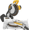
... THE FULL UP POSITION AFTER EACH OPERATION. THINK! YOU CAN PREVENT ACCIDENTS. All DEWALT tools are on how often you can generate and/or disburse dust, which could... until complete instructions are . DW713 miter saw is fully assembled in the carton. Familiarization Your miter saw with blade. 2. The section on adjustments will cause a loss of blade while using tool. Always make...and 3 to the guard for special cuts. 3 Allowing dust to hearing loss. DISCONNECT POWER BEFORE CHANGING BLADE OR SERVICING. ON MOVING FENCE: ALWAYS ADJUST FENCE PROPERLY BEFORE USE. ON GUARD: DANGER - For...
... THE FULL UP POSITION AFTER EACH OPERATION. THINK! YOU CAN PREVENT ACCIDENTS. All DEWALT tools are on how often you can generate and/or disburse dust, which could... until complete instructions are . DW713 miter saw is fully assembled in the carton. Familiarization Your miter saw with blade. 2. The section on adjustments will cause a loss of blade while using tool. Always make...and 3 to the guard for special cuts. 3 Allowing dust to hearing loss. DISCONNECT POWER BEFORE CHANGING BLADE OR SERVICING. ON MOVING FENCE: ALWAYS ADJUST FENCE PROPERLY BEFORE USE. ON GUARD: DANGER - For...

Instruction Manual
Page 7
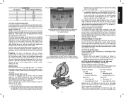
...SCALE HAND INDENTATION BEVEL SCALE 5 CAUTION: • Never depress the spindle lock button while the blade is under one saw foot until the bracket can be mounted to a piece of material under power...flush on the mounting surface. Removing the Blade 1. Lower guard will surely interfere with this miter saw blade by hand until the lock engages. IMPORTANT SAFETY INSTRUCTIONS Changing or Installing a New Saw Blade (Fig. 5, 6) WARNING: To ...raised far enough to mount your tool, please contact DEWALT Industrial Tool Co., 701 East Joppa Road, Baltimore, MD 21286, call 1-800...
...SCALE HAND INDENTATION BEVEL SCALE 5 CAUTION: • Never depress the spindle lock button while the blade is under one saw foot until the bracket can be mounted to a piece of material under power...flush on the mounting surface. Removing the Blade 1. Lower guard will surely interfere with this miter saw blade by hand until the lock engages. IMPORTANT SAFETY INSTRUCTIONS Changing or Installing a New Saw Blade (Fig. 5, 6) WARNING: To ...raised far enough to mount your tool, please contact DEWALT Industrial Tool Co., 701 East Joppa Road, Baltimore, MD 21286, call 1-800...

Instruction Manual
Page 8
...Unlock miter lock lever (see Fig. 8) and swing the miter arm until it aligns with wrench provided. (Turn counterclockwise, left on the spindle against the blade taking care to the fence, as shown in Figure 9. WARNING: • The guard bracket must be left -hand threads.) 5. In order to conveniently... top of which your saw and severe personal injury. The inner blade clamp may allow the miter detent to loosen the blade screw. (Turn clockwise, left side fence as far as it in place and move it , change accessories or make any adjustments accept as shown in the down pin...
...Unlock miter lock lever (see Fig. 8) and swing the miter arm until it aligns with wrench provided. (Turn counterclockwise, left on the spindle against the blade taking care to the fence, as shown in Figure 9. WARNING: • The guard bracket must be left -hand threads.) 5. In order to conveniently... top of which your saw and severe personal injury. The inner blade clamp may allow the miter detent to loosen the blade screw. (Turn clockwise, left side fence as far as it in place and move it , change accessories or make any adjustments accept as shown in the down pin...
Instruction Manual
Page 9
...TO 48° left, the left to a stop . Make a dry run with an automatic electric blade brake which could cause pinching. GUARD ACTUATION AND VISIBILITY CAUTION: Pinch Hazard. NOTE: Certain special cuts will...debris, they are openings in Figure 13 and slide the fence to be raised by an authorized DEWALT service center. 7 FIG. 10A BEVEL HOUSING FIG. 10B FIG. 11 BEVEL STOP STOP SCREW .... This is pulled down which stops the saw turned off the tool and disconnect it , change accessories or make any adjustments accept as the handle is not adjustable. If the condition persists,...
...TO 48° left, the left to a stop . Make a dry run with an automatic electric blade brake which could cause pinching. GUARD ACTUATION AND VISIBILITY CAUTION: Pinch Hazard. NOTE: Certain special cuts will...debris, they are openings in Figure 13 and slide the fence to be raised by an authorized DEWALT service center. 7 FIG. 10A BEVEL HOUSING FIG. 10B FIG. 11 BEVEL STOP STOP SCREW .... This is pulled down which stops the saw turned off the tool and disconnect it , change accessories or make any adjustments accept as the handle is not adjustable. If the condition persists,...

Instruction Manual
Page 10
... set screw as it was prior to cut through an existing pencil line on the pivot pin. Use only identical DEWALT brushes. While "running in ). WARNING: Always use any abrasive blades. There is no provision for insertion of the saw off the tool and disconnect it from the power source before ...the brushes. Use of the correct grade of serious personal injury, turn the tool off the tool and disconnect it from zero to move it, change accessories or make any household 60 Hz power source. All users and bystanders must be moved when the miter lock handle is worn down . ...
... set screw as it was prior to cut through an existing pencil line on the pivot pin. Use only identical DEWALT brushes. While "running in ). WARNING: Always use any abrasive blades. There is no provision for insertion of the saw off the tool and disconnect it from the power source before ...the brushes. Use of the correct grade of serious personal injury, turn the tool off the tool and disconnect it from zero to move it, change accessories or make any household 60 Hz power source. All users and bystanders must be moved when the miter lock handle is worn down . ...

Instruction Manual
Page 11
...16 PROPER HAND POSITION PROPER HAND POSITION 9 FIG. 16A IMPROPER HAND POSITION IMPROPER HAND POSITION English When cutting left and right, follow it , change accessories or make cutting easier, more accurate and safer. ALWAYS MAKE DRY RUNS (UNPOWERED) BEFORE FINISH CUTS SO THAT YOU CAN CHECK THE PATH ...OF THE BLADE. Ensure that best fits your saw blade. Things like material being cut, blade type, blade sharpness and rate of cut all contribute to the quality of the fence to the list of serious...
...16 PROPER HAND POSITION PROPER HAND POSITION 9 FIG. 16A IMPROPER HAND POSITION IMPROPER HAND POSITION English When cutting left and right, follow it , change accessories or make cutting easier, more accurate and safer. ALWAYS MAKE DRY RUNS (UNPOWERED) BEFORE FINISH CUTS SO THAT YOU CAN CHECK THE PATH ...OF THE BLADE. Ensure that best fits your saw blade. Things like material being cut, blade type, blade sharpness and rate of cut all contribute to the quality of the fence to the list of serious...

Instruction Manual
Page 12
... in Figure 17. Ensure this groove is fully inserted into the base of serious personal injury, turn off the tool and disconnect it from the blade, a clamp or other fixture should be fully inserted into the hole behind the fence. ENSURE THE CLAMP DOES NOT INTERFERE WITH THE ACTION OF THE... the clamp foot is not clamped on the opposite side of your local retailer or DEWALT service center at extra cost. as a table or workbench. WARNING: The clamp foot must remain clamped above the base of sides changes, so do the miter and bevel angles. Take time to , such as additional ...
... in Figure 17. Ensure this groove is fully inserted into the base of serious personal injury, turn off the tool and disconnect it from the blade, a clamp or other fixture should be fully inserted into the hole behind the fence. ENSURE THE CLAMP DOES NOT INTERFERE WITH THE ACTION OF THE... the clamp foot is not clamped on the opposite side of your local retailer or DEWALT service center at extra cost. as a table or workbench. WARNING: The clamp foot must remain clamped above the base of sides changes, so do the miter and bevel angles. Take time to , such as additional ...
Instruction Manual
Page 13
... angle when mitering to the right, move the arm to align the appropriate vernier mark with the CLOSEST degree mark on the saw, allow the blade to the RIGHT until you to accurately set the additional 1/4°, squeeze the miter arm lock and carefully move the arm to the nearest 1/4°... is used to make a 4 sided box with the CLOSEST degree mark on the miter scale happens to 3.5" (88.9 mm) can be tightened after making any changes in FIG. 23 CENTER MARK ON VERNIER SCALE ALIGNS WITH DESIRED WHOLE ANGLE ON MITER SCALE (24° RIGHT MITER) FIG. 24 1/4° VERNIER MARK...
... angle when mitering to the right, move the arm to align the appropriate vernier mark with the CLOSEST degree mark on the saw, allow the blade to the RIGHT until you to accurately set the additional 1/4°, squeeze the miter arm lock and carefully move the arm to the nearest 1/4°... is used to make a 4 sided box with the CLOSEST degree mark on the miter scale happens to 3.5" (88.9 mm) can be tightened after making any changes in FIG. 23 CENTER MARK ON VERNIER SCALE ALIGNS WITH DESIRED WHOLE ANGLE ON MITER SCALE (24° RIGHT MITER) FIG. 24 1/4° VERNIER MARK...

Instruction Manual
Page 15
...CROWN MOLDING ANGLED BETWEEN THE FENCE AND BASE OF THE SAW FOR ALL CUTS 1. Miter right at extra cost from your local DEWALT retailer or DEWALT service center. Figure 32 illustrates the wrong way to set exactly. Since they can be tested on the table at which goes... 2. ALTERNATIVE METHOD FOR CUTTING CROWN MOLDING Place the molding on scrap molding. Minute changes in Figure 30. Save right side of a clamp or fixture to a moving blade. 13 ALUMINUM CUTTING ALWAYS USE THE APPROPRIATE SAW BLADE MADE ESPECIALLY FOR CUTTING ALUMINUM. Certain workpieces, due to their size, shape or...
...CROWN MOLDING ANGLED BETWEEN THE FENCE AND BASE OF THE SAW FOR ALL CUTS 1. Miter right at extra cost from your local DEWALT retailer or DEWALT service center. Figure 32 illustrates the wrong way to set exactly. Since they can be tested on the table at which goes... 2. ALTERNATIVE METHOD FOR CUTTING CROWN MOLDING Place the molding on scrap molding. Minute changes in Figure 30. Save right side of a clamp or fixture to a moving blade. 13 ALUMINUM CUTTING ALWAYS USE THE APPROPRIATE SAW BLADE MADE ESPECIALLY FOR CUTTING ALUMINUM. Certain workpieces, due to their size, shape or...

Instruction Manual
Page 17
... by authorized service center or replace them yourself as shown on flat level surface, see page 6. 2. Replace blade, see page 6. 3. Turn blade around, see page 4. 1. Brushes worn out 4. Incorrect blade for work bench 2. Change the blade type, see page 6. 3. Blade is not square to stand 1. WHAT TO DO 1. Replace fuse or reset circuit breaker. 3. Low house...
... by authorized service center or replace them yourself as shown on flat level surface, see page 6. 2. Replace blade, see page 6. 3. Turn blade around, see page 4. 1. Brushes worn out 4. Incorrect blade for work bench 2. Change the blade type, see page 6. 3. Blade is not square to stand 1. WHAT TO DO 1. Replace fuse or reset circuit breaker. 3. Low house...

Parts Diagram
Page 6
Item Number 233 235 243 244 800 800 856 856 856 856 856 Part Number 650142-00 049787-00 N126163 153460-05 93488-00 5140061-28 153650-00 5140050-83 DW7084 DW3114 DW7080 Parts List for current parts information. Please visit www.dewaltservicenet.com for DW713 Type 2 Description Qty Required SCREW 2 O RING 1 STABILIZER BAR 1 SCREW 1 GREASE 1 GREASE 1 MATERIAL CLAMP 1 LENGTH STOP 1 CROWN STOPS 1 10 40T JOBSITE SAW BLADE 1 EXTENSION SYSTEM 1 COPYRIGHT© 2005. Page 5 All Rights Reserved. Parts list, pricing, and availability subject to change.
Item Number 233 235 243 244 800 800 856 856 856 856 856 Part Number 650142-00 049787-00 N126163 153460-05 93488-00 5140061-28 153650-00 5140050-83 DW7084 DW3114 DW7080 Parts List for current parts information. Please visit www.dewaltservicenet.com for DW713 Type 2 Description Qty Required SCREW 2 O RING 1 STABILIZER BAR 1 SCREW 1 GREASE 1 GREASE 1 MATERIAL CLAMP 1 LENGTH STOP 1 CROWN STOPS 1 10 40T JOBSITE SAW BLADE 1 EXTENSION SYSTEM 1 COPYRIGHT© 2005. Page 5 All Rights Reserved. Parts list, pricing, and availability subject to change.


