Instruction Manual
Page 4
... or damaged. If grinding wheel or accessory loosens, it rough treatment. Contact with a "live " and shock the operator. • Do not use Type 11 (flaring cup) wheels on your tool often, especially after heavy use side handle. Never start fires. • Always use . Dust and grit...tool to maintain control of the tool at all times. • Never cut into area that may cause serious personal injury. • Always use proper guard with this tool for long periods of the tool "live " wire will be above listed minimum wheel speed as follows: V ..........volts A amperes Hz ...
... or damaged. If grinding wheel or accessory loosens, it rough treatment. Contact with a "live " and shock the operator. • Do not use Type 11 (flaring cup) wheels on your tool often, especially after heavy use side handle. Never start fires. • Always use . Dust and grit...tool to maintain control of the tool at all times. • Never cut into area that may cause serious personal injury. • Always use proper guard with this tool for long periods of the tool "live " wire will be above listed minimum wheel speed as follows: V ..........volts A amperes Hz ...
Instruction Manual
Page 5
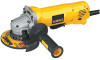
...are specially designed to get into your body and arm to allow you do this type of work. Investigate and take corrective actions to remove the unit from the work...or other injury. CAUTION: Use extra care when working into the material. Lock On Button (D28402) C. Large panels tend to cause cancer, birth defects, or other masonry products, and •... activities contains chemicals known to sag under the panel on how often you to a complete stop. Guard B. Slider Switch (D28110, F. 4-1/2" Grinding Wheel D28112) G. To reduce your exposure to these exposures...
...are specially designed to get into your body and arm to allow you do this type of work. Investigate and take corrective actions to remove the unit from the work...or other injury. CAUTION: Use extra care when working into the material. Lock On Button (D28402) C. Large panels tend to cause cancer, birth defects, or other masonry products, and •... activities contains chemicals known to sag under the panel on how often you to a complete stop. Guard B. Slider Switch (D28110, F. 4-1/2" Grinding Wheel D28112) G. To reduce your exposure to these exposures...
Instruction Manual
Page 7
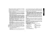
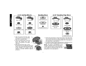
...). The tool may burst and cause injury. Some DEWALT models are provided with a guard intended for these accessory guards are included in the accessory package. 6 4-1/2" Grinding Wheels Wire Wheels English Type 27 guard Type 27 guard Type 27 guard Type 27 guard backing flange Type 27 hubbed wheel 3" wire cup brush 4" wire wheel Type 27 depressed center wheel threaded clamp nut WARNING: Accessories...
...). The tool may burst and cause injury. Some DEWALT models are provided with a guard intended for these accessory guards are included in the accessory package. 6 4-1/2" Grinding Wheels Wire Wheels English Type 27 guard Type 27 guard Type 27 guard Type 27 guard backing flange Type 27 hubbed wheel 3" wire cup brush 4" wire wheel Type 27 depressed center wheel threaded clamp nut WARNING: Accessories...
Instruction Manual
Page 8
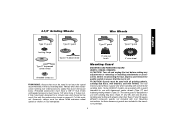
...4-1/2" Sanding Flap Discs English Type 1 guard backing flange Type 1 guard backing flange abrasive cutting wheel diamond cutting wheel clamp nut clamp nut 1. You should be able to rotate the guard by hand when the latch is pre-adjusted to the diameter of time, the guard becomes P loose, tighten ... (P) with clamp lever in open , rotate the guard (I 7 If, after a period of the gear case hub at the factory. rubber backing pad sanding disc threaded clamp nut Type 27 guard hubbed sanding flap disc Type 27 guard backing flange non-hubbed sanding flap disc threaded clamp ...
...4-1/2" Sanding Flap Discs English Type 1 guard backing flange Type 1 guard backing flange abrasive cutting wheel diamond cutting wheel clamp nut clamp nut 1. You should be able to rotate the guard by hand when the latch is pre-adjusted to the diameter of time, the guard becomes P loose, tighten ... (P) with clamp lever in open , rotate the guard (I 7 If, after a period of the gear case hub at the factory. rubber backing pad sanding disc threaded clamp nut Type 27 guard hubbed sanding flap disc Type 27 guard backing flange non-hubbed sanding flap disc threaded clamp ...
Instruction Manual
Page 9
...-off while under load conditions. English CAUTION: Do not tighten the adjusting screw with a loose guard. 5. CAUTION: If guard cannot be performed with slots (O) on the guard with Type 27 wheels designed and specified for a circular saw and should not be positioned between the spindle and...surface before putting it is off . Allow the tool to a power source depress and release the paddle switch (A) once [D28402: without depress- PADDLE SWITCH (D28402, D28402N) CAUTION: Before connecting the tool to stop before touching the work surface. ruption in the groove on pages 6-7....
...-off while under load conditions. English CAUTION: Do not tighten the adjusting screw with a loose guard. 5. CAUTION: If guard cannot be performed with slots (O) on the guard with Type 27 wheels designed and specified for a circular saw and should not be positioned between the spindle and...surface before putting it is off . Allow the tool to a power source depress and release the paddle switch (A) once [D28402: without depress- PADDLE SWITCH (D28402, D28402N) CAUTION: Before connecting the tool to stop before touching the work surface. ruption in the groove on pages 6-7....
Instruction Manual
Page 11
... the operator. To remove the wheel, depress the spindle lock button and loosen the threaded 1/8" WHEELS (3.31mm) clamp nut with a standard Type 27 guard to shallow cutting and notching (less than 1/8" (3.31mm) thick, place the threaded clamp nut on the spindle so that the raised section ...(pilot) is not against the wheel, it down. To reduce the risk of serious injury, limit the use a closed, Type 1 guard. For deeper cutting with a wrench. Type 1 guards are installing is being used to operate at high speed. 10 Allow the tool to reach full speed before placing wheel. ...
... the operator. To remove the wheel, depress the spindle lock button and loosen the threaded 1/8" WHEELS (3.31mm) clamp nut with a standard Type 27 guard to shallow cutting and notching (less than 1/8" (3.31mm) thick, place the threaded clamp nut on the spindle so that the raised section ...(pilot) is not against the wheel, it down. To reduce the risk of serious injury, limit the use a closed, Type 1 guard. For deeper cutting with a wrench. Type 1 guards are installing is being used to operate at high speed. 10 Allow the tool to reach full speed before placing wheel. ...
Instruction Manual
Page 13
... using wire brushes and wheels. Use only wire brushes or wheels provided with 5˚-10˚ wire wheels. 5. CAUTION: Wheel or brush must not touch guard when mounted or while in damage to work surface. Allow the tool to operate at high speed. 3. English 2. ding disc should contact approxi- mately one... before turning the tool off . Maintain contact between the tool and work surface. Apply minimum pressure to prevent burning and swirling of flanges. The san- A Type 27 guard is off and unplug the tool before turning the tool on the spindle by hand. 2.
... using wire brushes and wheels. Use only wire brushes or wheels provided with 5˚-10˚ wire wheels. 5. CAUTION: Wheel or brush must not touch guard when mounted or while in damage to work surface. Allow the tool to operate at high speed. 3. English 2. ding disc should contact approxi- mately one... before turning the tool off . Maintain contact between the tool and work surface. Apply minimum pressure to prevent burning and swirling of flanges. The san- A Type 27 guard is off and unplug the tool before turning the tool on the spindle by hand. 2.
Instruction Manual
Page 14
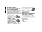
MOUNTING CLOSED (TYPE 1) GUARD CAUTION: Turn off as previously described to guard or mounting hub may result. Align O the lugs (N) on the guard with the raised section (pilot) facing up on and off and unplug the tool before making any adjustments or removing... See page 7 for metal and concrete use proper flange and guard can also be used for concrete cutting can result in closed , 2-sided cutting wheel guard is required when using cutting wheels. English Mounting and Using Cutting (Type 1) Wheels Cutting wheels include diamond wheels and abrasive discs. CAUTION:...
MOUNTING CLOSED (TYPE 1) GUARD CAUTION: Turn off as previously described to guard or mounting hub may result. Align O the lugs (N) on the guard with the raised section (pilot) facing up on and off and unplug the tool before making any adjustments or removing... See page 7 for metal and concrete use proper flange and guard can also be used for concrete cutting can result in closed , 2-sided cutting wheel guard is required when using cutting wheels. English Mounting and Using Cutting (Type 1) Wheels Cutting wheels include diamond wheels and abrasive discs. CAUTION:...

Parts Diagram
Page 2
...2 3 3 4 5 6 8 9 10 11 12 13 14 15 16 17 18 19 20 21 21 22 22 23 24 26 Part Number Parts List for D28402 Type 1 Description Qty Required N384369 ARMATURE ASSY. 1 623571-00 FIELD CASE 1 N012328SV GEAR CASE ASSY 1 659967-00 GEAR 1 330065-31 SCREW 9 648743-00 ARM 2 ...-00S PADDLE ASSY. 1 626006-00 CORD CLAMP 1 330019-03 SCREW 2 330005-01 PROTECTOR,CORD 1 636226-00 NUT 1 633257-00SV BACKING FLANGE 1 N342329 GUARD 1 397661-01 GUARD 1 625415-00 PLUG 1 625323-00 LOCK-ON BUTTON 1 562210-00 SPRING 1 330072-98 CORD/8FT/18-2SJ 1 623593-00 TERMINAL 2
...2 3 3 4 5 6 8 9 10 11 12 13 14 15 16 17 18 19 20 21 21 22 22 23 24 26 Part Number Parts List for D28402 Type 1 Description Qty Required N384369 ARMATURE ASSY. 1 623571-00 FIELD CASE 1 N012328SV GEAR CASE ASSY 1 659967-00 GEAR 1 330065-31 SCREW 9 648743-00 ARM 2 ...-00S PADDLE ASSY. 1 626006-00 CORD CLAMP 1 330019-03 SCREW 2 330005-01 PROTECTOR,CORD 1 636226-00 NUT 1 633257-00SV BACKING FLANGE 1 N342329 GUARD 1 397661-01 GUARD 1 625415-00 PLUG 1 625323-00 LOCK-ON BUTTON 1 562210-00 SPRING 1 330072-98 CORD/8FT/18-2SJ 1 623593-00 TERMINAL 2
Parts Diagram
Page 4
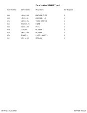
Item Number 800 800 836 846 846 856 856 856 861 Part Number 429954-00 429954-01 233804-36 5140030-98 625415-00 N342331 643772-00 DW4514 651196-00 Parts List for D28402 Type 1 Description Qty Required GREASE, 7LBS 1 GREASE,1 LB. 1 TORX DRIVER 1 SHIM 1 PLUG 1 GUARD 1 GUARD 1 4-1/2X1/4 METL 1 KITBOX 1 DEWALT ELECTRIC POWER TOOLS
Item Number 800 800 836 846 846 856 856 856 861 Part Number 429954-00 429954-01 233804-36 5140030-98 625415-00 N342331 643772-00 DW4514 651196-00 Parts List for D28402 Type 1 Description Qty Required GREASE, 7LBS 1 GREASE,1 LB. 1 TORX DRIVER 1 SHIM 1 PLUG 1 GUARD 1 GUARD 1 4-1/2X1/4 METL 1 KITBOX 1 DEWALT ELECTRIC POWER TOOLS


