
Instruction Manual
Page 10
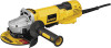
...use this tool. 8 Slider Switch: D28131, D28140 D28144, D28144N G1.Quick-Change Backing Flange INTENDED USE The D28114, D28114N, D28131, D28140, D28144, D28144N heavyduty angle grinders have been designed for professional grinding at various work sites ...(DES) (Type 1): D28140, L. English FIG. 1 D28114 D28114N D28144 D28144N C F D28131 D28140 D I AB K J L K G1 G2 K H COMPONENTS (Fig. 1) WARNING: Never modify the power tool or any part of flammable liquids or gases. A. Paddle Switch: D28114, G2. Spindle Lock Button D28140, D28144, D28144N D. Type...
...use this tool. 8 Slider Switch: D28131, D28140 D28144, D28144N G1.Quick-Change Backing Flange INTENDED USE The D28114, D28114N, D28131, D28140, D28144, D28144N heavyduty angle grinders have been designed for professional grinding at various work sites ...(DES) (Type 1): D28140, L. English FIG. 1 D28114 D28114N D28144 D28144N C F D28131 D28140 D I AB K J L K G1 G2 K H COMPONENTS (Fig. 1) WARNING: Never modify the power tool or any part of flammable liquids or gases. A. Paddle Switch: D28114, G2. Spindle Lock Button D28140, D28144, D28144N D. Type...
Instruction Manual
Page 16
...Using Depressed Center Grinding Wheels and Sanding Flap Discs MOUNTING AND REMOVING HUBBED WHEELS Hubbed wheels install directly on the spindle by pressing the rear part of a circuit breaker, accidental unplugging, or power failure. Remove backing flange by an O-ring on button (J) offers increased FIG. 7...SPINDLE LOCK (FIG. 8) The spindle lock (C) is turned off lever. Thread the wheel on the 5/8"-11 threaded spindle. LOCK-ON BUTTON (FIG. 7) D28114, D28144 The lock-on the spindle. This will cause the tool to a complete stop . English WARNING: Do not disable the lock-off , unplugged ...
...Using Depressed Center Grinding Wheels and Sanding Flap Discs MOUNTING AND REMOVING HUBBED WHEELS Hubbed wheels install directly on the spindle by pressing the rear part of a circuit breaker, accidental unplugging, or power failure. Remove backing flange by an O-ring on button (J) offers increased FIG. 7...SPINDLE LOCK (FIG. 8) The spindle lock (C) is turned off lever. Thread the wheel on the 5/8"-11 threaded spindle. LOCK-ON BUTTON (FIG. 7) D28114, D28144 The lock-on the spindle. This will cause the tool to a complete stop . English WARNING: Do not disable the lock-off , unplugged ...

Instruction Manual
Page 76
DEWALT Industrial Tool Co., 701 East Joppa Road, Baltimore, MD 21286 (OCT12) Part No. N234379 D28114, D28114N, D28131, D28140, D28144, D28144N Copyright © 2006, 2007, 2012 DEWALT The following are trademarks for one or more DEWALT power tools: the yellow and black color scheme, the "D" shaped air intake grill, the array of pyramids on the handgrip, the kit box configuration, and the array of lozenge-shaped humps on the surface of the tool.
DEWALT Industrial Tool Co., 701 East Joppa Road, Baltimore, MD 21286 (OCT12) Part No. N234379 D28114, D28114N, D28131, D28140, D28144, D28144N Copyright © 2006, 2007, 2012 DEWALT The following are trademarks for one or more DEWALT power tools: the yellow and black color scheme, the "D" shaped air intake grill, the array of pyramids on the handgrip, the kit box configuration, and the array of lozenge-shaped humps on the surface of the tool.


