Mobile Precision Re-Image Guide
Page 27
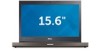
...M4600 M6600 E6430 ATG M4700 M6700 Digitech Touch Screen X eGalax EMPIA n-Trig Multi Touch X X X X X X X X X 2.6.21 Webcam -applies to be installed after the AMT Unified driver 4. For E-Family 4th generation systems, Intel Unified AMT 8 Management Interface Driver Intel Identity Protection Technology (IPT) feature was included in system digital camera...32 & 64-Bit Operating Systems do not include the USB 3.0 driver. Dell Latitude Ultrabook, E-Family & Mobile Precision Reimage "How-To" Guide Intel Identity Protection Technology (IPT) feature requires...
...M4600 M6600 E6430 ATG M4700 M6700 Digitech Touch Screen X eGalax EMPIA n-Trig Multi Touch X X X X X X X X X 2.6.21 Webcam -applies to be installed after the AMT Unified driver 4. For E-Family 4th generation systems, Intel Unified AMT 8 Management Interface Driver Intel Identity Protection Technology (IPT) feature was included in system digital camera...32 & 64-Bit Operating Systems do not include the USB 3.0 driver. Dell Latitude Ultrabook, E-Family & Mobile Precision Reimage "How-To" Guide Intel Identity Protection Technology (IPT) feature requires...

Owner's Manual (M4600)
Page 7
...Camera 105 Removing The Camera 105 Installing The Camera 106 34 Display Hinge Cap Tower 107 Removing The Display Hinge Cap Tower 107 Installing The Display Hinge Cap Tower 109 35 Low-Voltage Differential Signaling (LVDS) Camera Cable............111 Removing The Low-Voltage Differential Signaling (LVDS) Camera... Cable 111 Installing The Low-Voltage Differential Signaling (LVDS) Camera...) Cable 114 Removing The RGB Camera Cable 114 Installing The RGB Camera Cable 116 36 Specifications 117 Technical...
...Camera 105 Removing The Camera 105 Installing The Camera 106 34 Display Hinge Cap Tower 107 Removing The Display Hinge Cap Tower 107 Installing The Display Hinge Cap Tower 109 35 Low-Voltage Differential Signaling (LVDS) Camera Cable............111 Removing The Low-Voltage Differential Signaling (LVDS) Camera... Cable 111 Installing The Low-Voltage Differential Signaling (LVDS) Camera...) Cable 114 Removing The RGB Camera Cable 114 Installing The RGB Camera Cable 116 36 Specifications 117 Technical...

Owner's Manual (M4600)
Page 77
14. Disconnect the camera cable. 77 Disconnect the LVDS cable. 16. Loosen the captive screws securing the Low-voltage Differential Signaling (LVDS) cable in place. 15.
14. Disconnect the camera cable. 77 Disconnect the LVDS cable. 16. Loosen the captive screws securing the Low-voltage Differential Signaling (LVDS) cable in place. 15.

Owner's Manual (M4600)
Page 79
... Install the base cover. 16. Connect antennas to the routing channels. 9. Install the battery. 17. Installing The Display Assembly 1. Install the keyboard. 14. Connect the camera cable to the bottom of the computer. 2. Install the optical drive. 13.
... Install the base cover. 16. Connect antennas to the routing channels. 9. Install the battery. 17. Installing The Display Assembly 1. Install the keyboard. 14. Connect the camera cable to the bottom of the computer. 2. Install the optical drive. 13.

Owner's Manual (M4600)
Page 105
Follow the procedures in Before Working On Your Computer 2. Remove the standard display bezel or the touchscreen display bezel. 4. Disconnect the camera cable. 6. Remove the standard display panel or the touchscreen display panel. 5. Remove the battery. 3. Lift and remove the camera and microphone module. 105 Loosen the screw securing the camera and microphone module. 7. Camera 33 Removing The Camera 1.
Follow the procedures in Before Working On Your Computer 2. Remove the standard display bezel or the touchscreen display bezel. 4. Disconnect the camera cable. 6. Remove the standard display panel or the touchscreen display panel. 5. Remove the battery. 3. Lift and remove the camera and microphone module. 105 Loosen the screw securing the camera and microphone module. 7. Camera 33 Removing The Camera 1.

Owner's Manual (M4600)
Page 106
Install the standard display panel or the touchscreen display panel. 5. Follow the procedures in place. 2. Place the camera and microphone module on the display cover and tighten the screw securing the camera and microphone module in After Working Inside Your Computer. 106 Install the standard display bezel or the touchscreen display bezel. 6. Installing The Camera 1. Install the battery. 4. Connect the camera cable to the camera and microphone module. 3.
Install the standard display panel or the touchscreen display panel. 5. Follow the procedures in place. 2. Place the camera and microphone module on the display cover and tighten the screw securing the camera and microphone module in After Working Inside Your Computer. 106 Install the standard display bezel or the touchscreen display bezel. 6. Installing The Camera 1. Install the battery. 4. Connect the camera cable to the camera and microphone module. 3.

Owner's Manual (M4600)
Page 111
... 35 Removing The Low-Voltage Differential Signaling (LVDS) Camera Cable 1. Follow the procedures in Before Working On Your Computer. 2. Remove the base cover. 4. Remove the optical drive. 7. Remove the standard display bezel or the ... the battery. 3. Remove the palm rest. 9. Remove the standard display panel or the touchscreen display panel. 12. Disconnect the low-voltage differential signaling (LVDS) and camera cable from the display cover. 111 Remove the display hinge, hinge cap, hinge tower. 13. Remove the keyboard. 6. Pry up the LVDS and...
... 35 Removing The Low-Voltage Differential Signaling (LVDS) Camera Cable 1. Follow the procedures in Before Working On Your Computer. 2. Remove the base cover. 4. Remove the optical drive. 7. Remove the standard display bezel or the ... the battery. 3. Remove the palm rest. 9. Remove the standard display panel or the touchscreen display panel. 12. Disconnect the low-voltage differential signaling (LVDS) and camera cable from the display cover. 111 Remove the display hinge, hinge cap, hinge tower. 13. Remove the keyboard. 6. Pry up the LVDS and...

Owner's Manual (M4600)
Page 112
...3. Install the display assembly. 8. Install the palm rest. 9. Install the optical drive. 11. Remove the palm rest. 9. Replace the adhesives to the camera. 4. Install the keyboard trim. 13. Removing The RGB Low-voltage Differential Signaling (LVDS) Cable 1. Remove the keyboard trim. 5. Install the standard display .... Remove the base cover. 4. Install the keyboard. 12. Install the base cover. 14. Installing The Low-Voltage Differential Signaling (LVDS) Camera Cable 1. Secure the low-voltage differential signaling (LVDS) cable to its routing channel. 2.
...3. Install the display assembly. 8. Install the palm rest. 9. Install the optical drive. 11. Remove the palm rest. 9. Replace the adhesives to the camera. 4. Install the keyboard trim. 13. Removing The RGB Low-voltage Differential Signaling (LVDS) Cable 1. Remove the keyboard trim. 5. Install the standard display .... Remove the base cover. 4. Install the keyboard. 12. Install the base cover. 14. Installing The Low-Voltage Differential Signaling (LVDS) Camera Cable 1. Secure the low-voltage differential signaling (LVDS) cable to its routing channel. 2.

Owner's Manual (M4600)
Page 114
... Before Working On Your Computer. 2. Install the display assembly. 7. Install the hard drive. 9. Install the base cover. 13. Install the battery. 14. Removing The RGB Camera Cable 1. Follow the procedures in place. 3. Remove the keyboard trim. 5. Install the RGB display panel. 5. Install the keyboard. 11. Install the keyboard trim. 12. Remove...
... Before Working On Your Computer. 2. Install the display assembly. 7. Install the hard drive. 9. Install the base cover. 13. Install the battery. 14. Removing The RGB Camera Cable 1. Follow the procedures in place. 3. Remove the keyboard trim. 5. Install the RGB display panel. 5. Install the keyboard. 11. Install the keyboard trim. 12. Remove...

Owner's Manual (M4600)
Page 115
15. Pry up the camera cable from the display cover and remove the camera cable. 115
15. Pry up the camera cable from the display cover and remove the camera cable. 115

Owner's Manual (M4600)
Page 116
... in After Working Inside Your Computer. 116 Install the display assembly. 9. Install the keyboard. 13. Installing The RGB Camera Cable 1. Place the camera cable on the display cover. 2. Install the RGB Low-Voltage Differential Signaling (LVDS) cable. 5. Install the touch screen display bezel. 8. Install the ... the display hinge, hinge cap, hinge tower. 6. Install the optical drive. 12. Install the palm rest. 10. Replace the adhesives to the camera and microphone module. 4. Install the base cover. 15. Install the hard drive. 11. Follow the procedures in place. 3.
... in After Working Inside Your Computer. 116 Install the display assembly. 9. Install the keyboard. 13. Installing The RGB Camera Cable 1. Place the camera cable on the display cover. 2. Install the RGB Low-Voltage Differential Signaling (LVDS) cable. 5. Install the touch screen display bezel. 8. Install the ... the display hinge, hinge cap, hinge tower. 6. Install the optical drive. 12. Install the palm rest. 10. Replace the adhesives to the camera and microphone module. 4. Install the base cover. 15. Install the hard drive. 11. Follow the procedures in place. 3.
Owner's Manual (M4600)
Page 126
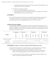
... or disable the following devices: • Internal Modem • Microphone • eSATA Ports • Hard Drive Free Fall Protection • Module Bay • ExpressCard • Camera You can also enable or disable: • Media Card and 1394 • Enable Media Card only • Disable Media Card and 1394 Default Setting: Media...
... or disable the following devices: • Internal Modem • Microphone • eSATA Ports • Hard Drive Free Fall Protection • Module Bay • ExpressCard • Camera You can also enable or disable: • Media Card and 1394 • Enable Media Card only • Disable Media Card and 1394 Default Setting: Media...
Setup and Features Information Tech Sheet
Page 1
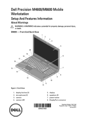
DisplayPort connector Regulatory Model: P13F, P10E Regulatory Type: P13F001, P10E001 January 2011 display latches (2) 2. camera LED 5. speakers (2) 7. microphones (2) 3. camera 4. power button 8. Front And Back View Figure 1. Front View 1. Dell Precision M4600/M6600 Mobile Workstation Setup And Features Information About Warnings WARNING: A WARNING indicates a potential for property damage, personal injury, or death. display 6. M4600 -
DisplayPort connector Regulatory Model: P13F, P10E Regulatory Type: P13F001, P10E001 January 2011 display latches (2) 2. camera LED 5. speakers (2) 7. microphones (2) 3. camera 4. power button 8. Front And Back View Figure 1. Front View 1. Dell Precision M4600/M6600 Mobile Workstation Setup And Features Information About Warnings WARNING: A WARNING indicates a potential for property damage, personal injury, or death. display 6. M4600 -
Setup and Features Information Tech Sheet
Page 3
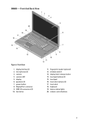
Front View 1. speakers (2) 7. microphones (2) 3. camera LED 5. DisplayPort connector 9. hard drive 11. wireless switch 13. keyboard 19. display latches (2) 2. fingerprint reader (optional) 12. track stick 18. display 6. touchpad buttons (3) 15. volume control buttons 3 M6600 - camera 4. Front And Back View Figure 3. power button 8. device status lights 20. USB 3.0 connectors (2) 10. track stick buttons (3) 17. display latch release button 14. touchpad 16.
Front View 1. speakers (2) 7. microphones (2) 3. camera LED 5. DisplayPort connector 9. hard drive 11. wireless switch 13. keyboard 19. display latches (2) 2. fingerprint reader (optional) 12. track stick 18. display 6. touchpad buttons (3) 15. volume control buttons 3 M6600 - camera 4. Front And Back View Figure 3. power button 8. device status lights 20. USB 3.0 connectors (2) 10. track stick buttons (3) 17. display latch release button 14. touchpad 16.

